The Measurement Chain
Today, measurement technology has a lot to do with electrical engineering. The main reason is that we increasingly prepare measurement results not for people who read them off measuring instruments, but for machines. In the digital world, machines need digital measurement data. There is only one quantity that can be digitised directly: electrical voltage. Very rarely, times or electric currents are also digitised, but again only as electrical quantities.
For this reason, all physical quantities that are measured and digitised in the process are converted into an electrical voltage. This happens in several steps, which are discussed one after the other in this lecture. The components involved in the signal processing are also called the “measurement chain”.
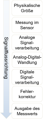
This introduction briefly covers the processing steps that are discussed in detail in the course of the lecture.
Sensors
Sensors convert physical quantities into analogue electrical quantities. Electrical quantities are, for example, current, voltage, frequency, resistance value or also time information that shows up in electrical quantities. There are, for example, temperature-dependent resistors whose resistance value changes with temperature.
Sensors are technical sense organs. They give technical systems information about the environment, as the eyes or the skin do for humans. Sensors are generally bought in and not developed in-house. Your task is therefore limited to choosing the sensor that suits the application (accuracy, robustness, cost).
It is generally difficult to convert a physical quantity into an electrical quantity in a sensor at all. The electrical quantity changes only very slightly with the physical quantity. The output voltage of a sensor is often only in the range of a few mV.
The “measuring range” of a sensor indicates which part of a physical quantity it can measure. The distance sensor of a robot vacuum cleaner, for example, has a typical measuring range of [0 cm .. 30 cm]. It can thus detect obstacles at a distance between 0 cm and 30 cm. The notation in square brackets indicates a range and not a single number.
Analogue-to-digital converter
An analogue-to-digital converter (ADC) outputs a number that is proportional to the input voltage. This number can, for example, be processed further in a microcontroller (Arduino). Analogue-to-digital conversion often takes place inside a microcontroller. The input voltage range of an ADC is typically [0 V .. 3 V] or [0 V .. 5 V].
In the measurement chain, an ADC comes after the analogue signal processing. It is discussed here first because the ADC defines the requirements for the analogue signal processing. Whatever electrical quantity the sensor outputs, it must be converted for the ADC into a voltage in the range of, for example, [0 V .. 3 V].
Analogue signal processing
The analogue signal processing forms the link between the sensor and the ADC. Its main task is to convert the electrical quantity at the sensor output into a voltage. If the temperature is to be measured with a temperature-dependent resistor, the temperature first changes the resistance value of the sensor. In the analogue signal processing, a change in voltage is generated from the change in resistance.
This voltage must then be amplified so that it fits the input voltage range of the AD converter. If, for example, the distance sensor of the robot vacuum cleaner converts the distance [0 cm .. 30 cm] into an output voltage in the range [0 V .. 30 mV] and the ADC has an input voltage range of [0 V .. 3 V], we have to amplify the sensor voltage by a factor of 100.
Microcontroller
The measurement signal passes through the following processing steps in the microcontroller:
1. Analogue-to-digital conversion
Almost all microcontrollers provide one or more ADCs with which voltages can be converted into numbers. The voltage range lies between 0 V and the ADC's “reference voltage”. The value of the reference voltage differs between ADCs. It is defined in each case in the ADC's data sheet. So the input voltage range is
2. Digital signal processing and error correction
In this block, software is programmed to change the number output by the ADC further. The output value can, for example, be corrected, or a unit can be assigned to it. This part fills your ISD studies in the “Embedded” specialisation.