Complex Electrical Quantities
Let us look at voltages and currents as complex numbers. In doing so, we change two parameters. First, for calculating AC networks it is helpful to choose the angular frequency ω instead of the frequency f as the parameter on the x-axis. The advantage only becomes clear when we look at energy stores with alternating current in a few chapters. To convert f into ω, we simply multiply by the factor 2π. The following applies: ω = 2πf.
Then we change the angle notation from DEG (the one with °) to RAD (the one with π). For the conversion, please use the following representation:
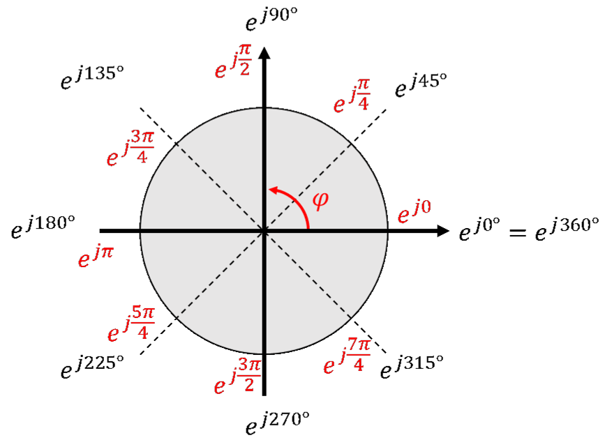
Please set your calculator to RAD, otherwise all your results will be wrong. Calculating in RAD instead of DEG is an arbitrary convention; of course you can also calculate everything in DEG. You have to decide on one angle representation, and I have decided on RAD. In my opinion, it has neither advantages nor disadvantages.
First, we convert example voltage curves from the time domain u(t) into complex numbers u(ω). The following applies:
In electrical engineering, complex numbers are often underlined. Strictly speaking, all complex voltages, currents etc. must always be underlined. Otherwise a DC voltage could not be distinguished from a purely real sinusoidal voltage with the same peak value. This chapter, however, is only about alternating current, so out of laziness I spare myself this. AC quantities use lower-case letters and DC quantities use upper-case letters. That has to be enough.
Exercise
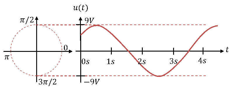
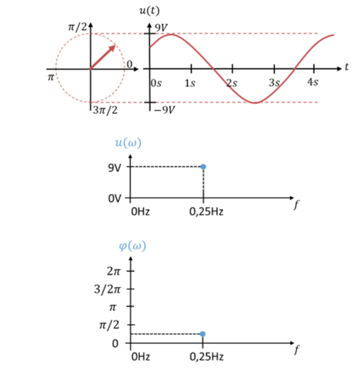
a) Determine the parameters peak value, period, frequency, angular frequency and phase angle of the voltage u(t).
b) Describe the voltage mathematically in the time domain.
c) Describe the voltage in the frequency domain in exponential form and in component form.
d) Draw the vector that indicates the peak value and angle into the circle in the left part of the figure.
e) Draw peak value and phase into a diagram in which both quantities are plotted over frequency.
Solution:
Typical rotation operators
When we write rotation operators in exponential form, they automatically have length 1. When we describe directions in component form, we first have to build a normalised direction vector of length 1 from them.
The direction 0° points to the right in the complex plane. The rotation operator ej0 therefore points to +1 on the real axis. We can give the directions of the 4 main axes relatively easily as direction vectors:
We can also give the bisectors in between in component form. To do this, let us look at a rotation by the angle 45° or π/4:
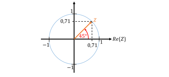
We build the direction vector from a positive real part and a positive imaginary part. Real and imaginary parts are smaller than the length of the vector.
We construct other bisectors according to a similar scheme:
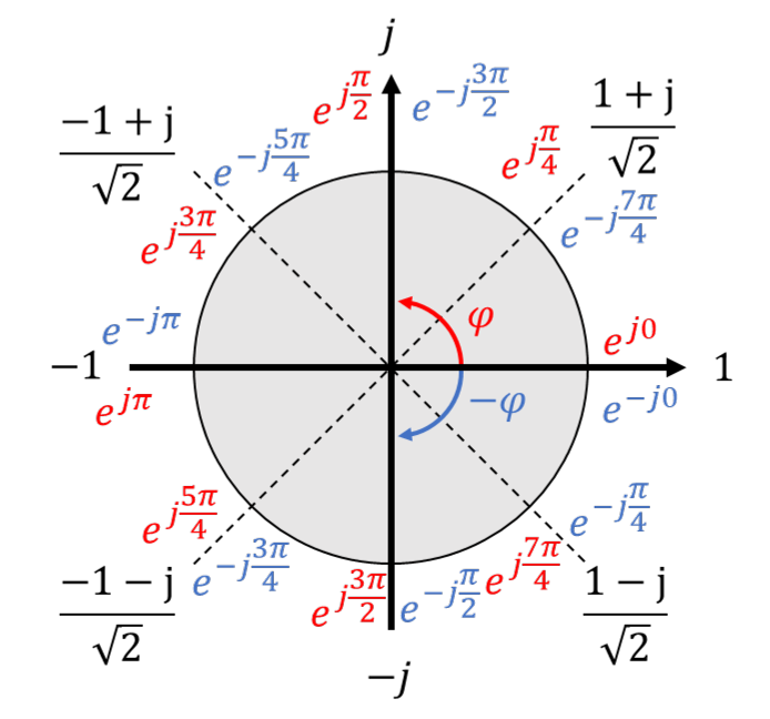
The figure above contains various forms of representation of typical angles. In black, the angles are given in component form. In red, the angles are given in RAD in the positive direction. If we reverse the sign in the exponent, we go around the circle clockwise. This gives the blue notations. All notations represent the same 8 angles.
Multiplication by j
In complex AC analysis with energy stores (later), we often multiply terms by j or by −j. A multiplication by j rotates a vector by 90° or π/2 anticlockwise. A multiplication by −j rotates a vector by 90° or π/2 clockwise. These multiplications are pure rotation operations, because the length of each operator is 1. So they do not change the vector length.
A multiplication by j∙j rotates twice by π/2, i.e. by the angle π in total. If I start at φ = 0 (i.e. at +1 on the real axis) and rotate by the angle π, I end up at the point −1 on the real axis. The mathematicians' statement that j∙j = −1 can easily be understood with these rotations.
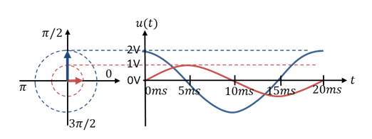
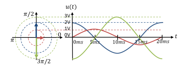
In the following figure, ublue = j ∙ 2 ∙ ured. The peak value of the blue curve is higher than that of the red curve by a factor of 2. The phase of the blue curve is shifted to the “left” by π/2. This corresponds to a multiplication by the factor j.