Inverting Amplifier
The second basic op-amp circuit is the inverting amplifier. Its circuit is similar to that of the non-inverting amplifier. Only the sensor signal is connected to the amplifier circuit at a different point.
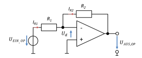
Problem: calculate the gain v of the circuit as a function of the resistors yourself. This lets you check whether you can calculate with meshes on op-amps. If you are presented with circuits other than these two basic circuits, you should master this procedure. The solution is given below the figure for checking.
With this amplifier, the signals are amplified and inverted at the same time. They are multiplied by a negative factor. Positive input voltages become negative at the output and negative ones become positive. Gain factors in the range v = [−1 … 0] are also possible. So this amplifier can also attenuate signals.
You have now got to know two basic circuits with which you can multiply input voltages by an adjustable factor. I will work through two example applications for you.
Example 1
A sensor outputs a sensor voltage in the range US = [0 V … 10 mV]. The ADC has a reference voltage of UREF = 5 V. The ADC is connected directly to the output of the op-amp of the analogue signal processing. So UAUS,OP = UEIN,ADC.
Problem: find a circuit with which the range of the sensor voltage can be mapped onto the ADC input voltage range.
Solution: to do this, the sensor voltage must be multiplied by a factor. Let us first determine this gain factor:
To fulfil this function, we need an amplifier circuit with a positive gain, i.e. the non-inverting op-amp.
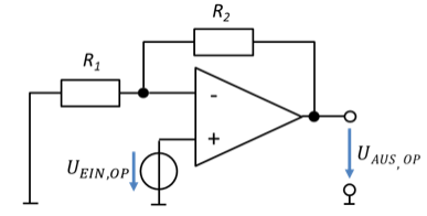
If we arbitrarily set R1 = 1 kΩ, then R2 must be 500 kΩ. In practice, we often round such values if the effect of rounding is less than 1 %. You can choose one resistor freely; the other then follows from the formula. The order of magnitude of the resistors can be chosen freely; only the ratio of the resistors is fixed. So there is not just one solution for dimensioning the resistors, but many.
Resistors for use in circuits are available in the range of values R = [10 mΩ … 10 MΩ]. For op-amp circuits, we usually choose resistors in the kΩ range, because the higher the resistance values, the less current flows in the circuit. This is particularly important in battery-powered applications.
Example 2
A sensor outputs a sensor voltage in the range US = [−100 µV .. 0 V]. The ADC has a reference voltage of UREF = 3 V.
Problem: find a circuit with which the range of the sensor voltage can be mapped onto the ADC input voltage range.
Solution: to do this, the sensor voltage must be multiplied by a factor. Let us first determine this gain factor:
Because we need a negative gain, in this case we use the inverting amplifier.
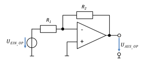
If we set R1 = 10 Ω, then R2 must be 300 kΩ. The current flows through both resistors. That is why it is sufficient for one of the resistors to have a high resistance in order to keep the current small.