Potential and Voltage
The state of charge at a location is described by the term electric potential φ. The greater the excess of electrons in a body, the more negative its potential. With a deficiency of electrons, the potential of a body is positive. The potential is linked to the charge of the bodies and their distance from each other. Electrostatics defines this relationship more precisely; we do without this here. For an intuitive understanding, it is sufficient to regard potential and charge as similar or related quantities.
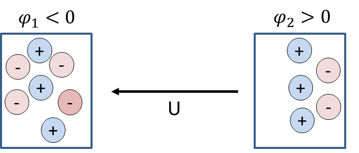
The electric voltage U is defined as the difference between two potentials. Between the two bodies, a voltage
can be measured. The value of the voltage is positive if the voltage arrow points from the higher to the lower potential. A voltage is also measured between two positively charged bodies if one of them is more positively charged than the other. So a voltage indicates a difference in charge.
The unit of voltage is the volt. Then the unit of potential must also be the volt, because the same unit must always appear on the left and right of an equation. You probably already know the volt.
| Physical quantity | Symbol | Unit name | Unit symbol |
|---|---|---|---|
| Potential | \(\varphi\) | volt | \(\mathrm{V} = \dfrac{\mathrm{Nm}}{\mathrm{As}}\) |
| Voltage | \(U\) | volt | \(\mathrm{V} = \dfrac{\mathrm{Nm}}{\mathrm{As}}\) |
Voltages are familiar from everyday life. A socket supplies a voltage of U = 230 V. A LiPo battery, such as the one built into a smartphone, has a voltage of U = 3.7 V. Voltage is the measure of the force acting on the electrons due to charge separation.
Aside: Besides electric voltage, there is also mechanical stress (in German both are called "Spannung"). In this text, electric voltage is always meant. This also applies to other electrical quantities. They are introduced once as electrical quantities; after that, out of laziness, I leave out the word "electric".
Electric voltage is comparable to the tension of a spring. Both cause a force. You can imagine a charged battery, which has an electric voltage at its terminals, as a tensioned spring. It is just waiting for the energy stored in it to be released.
The direction of the voltage
Let us consider two bodies, each with an excess of electrons. Body 1 has 5 electrons too many, body 2 has 3 electrons too many.
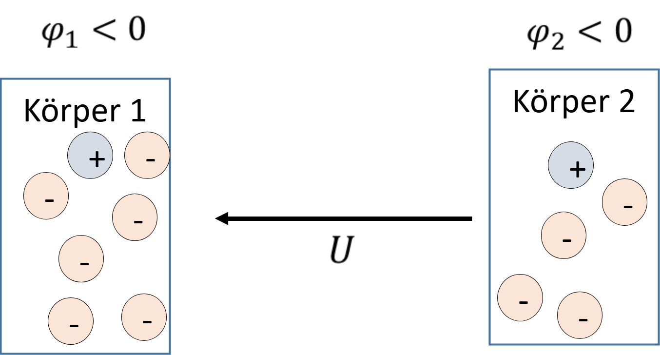
Both bodies have a negative potential, but body 1 is more negatively charged than body 2. That is why a voltage acts that is positive from body 2 towards body 1. The voltage is positive if the arrow points from the relatively higher to the lower potential.
If a path for the electrons is provided between these bodies, a current flows from body 1 towards body 2 due to the voltage. The charges balance out so that afterwards both bodies have 4 electrons too many. So charge balancing works independently of the number of charges; it is guided much more by the difference between charges. The result of a charge balance is therefore not always two electrically neutral, uncharged bodies, but two equally charged bodies. This also applies to different deficiencies of charge between two bodies. If 10000 electrons are missing on body 3 while 9000 electrons are missing on body 4, after a charge balance there is a deficiency of 9500 electrons on both bodies.
The voltage is the difference between two potentials. Let us consider an example with other bodies with other charges:
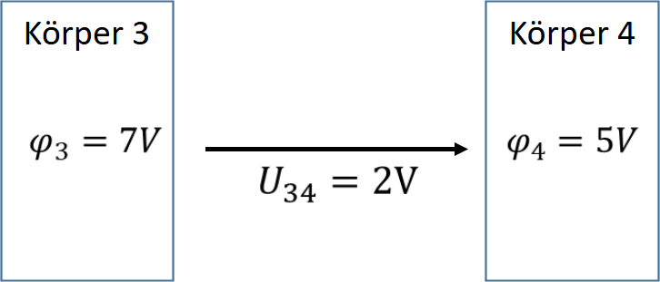
The voltage can also be drawn the other way round; then the following applies:
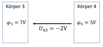
As a result, reversing the direction of the arrow changes the sign of the value. So the direction of the arrow in your sketch defines the sign of the voltage.
Calculating with potentials and voltages
Example: we consider a system with three bodies that have three potentials.
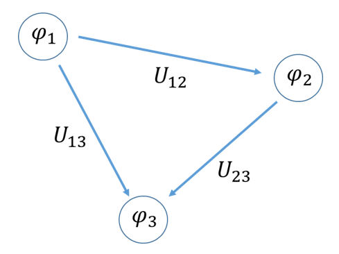
The voltages are calculated according to the arrow direction given in the sketch.
A voltage as the difference between two potentials is easy to calculate. The problem lies in stating the direction and the sign correctly. The sign is always correct if you calculate the potential at the tail of the voltage arrow minus the potential at the head of the voltage arrow. If the voltage arrow points from the larger to the smaller potential, the value of the voltage is positive.
Choice of the reference point
It is even simpler: let us go back mentally to the example in which a stone is lifted and then dropped. Assume the stone is lifted to h2 = 2 m and then falls to the floor. We intuitively define the height of the floor as the zero point of the system with h1 = 0 m.
The stone falls down by the height difference Δh = h2 – h1 = 2 m – 0 m = 2 m. But if there were no floor, the stone would fall further. The true zero point is the centre of the Earth, because that is where the stone actually wants to fall; it is the lowest possible point. In reality, the stone has fallen from a height of about h2 = 6371002 m to h1 = 6371000 m. In the locally limited experiment, however, we define the locally lowest point as the zero point. No matter where we place the zero point, the stone falls 2 metres, because the difference Δh = h2 – h1 is 2 m in both cases.
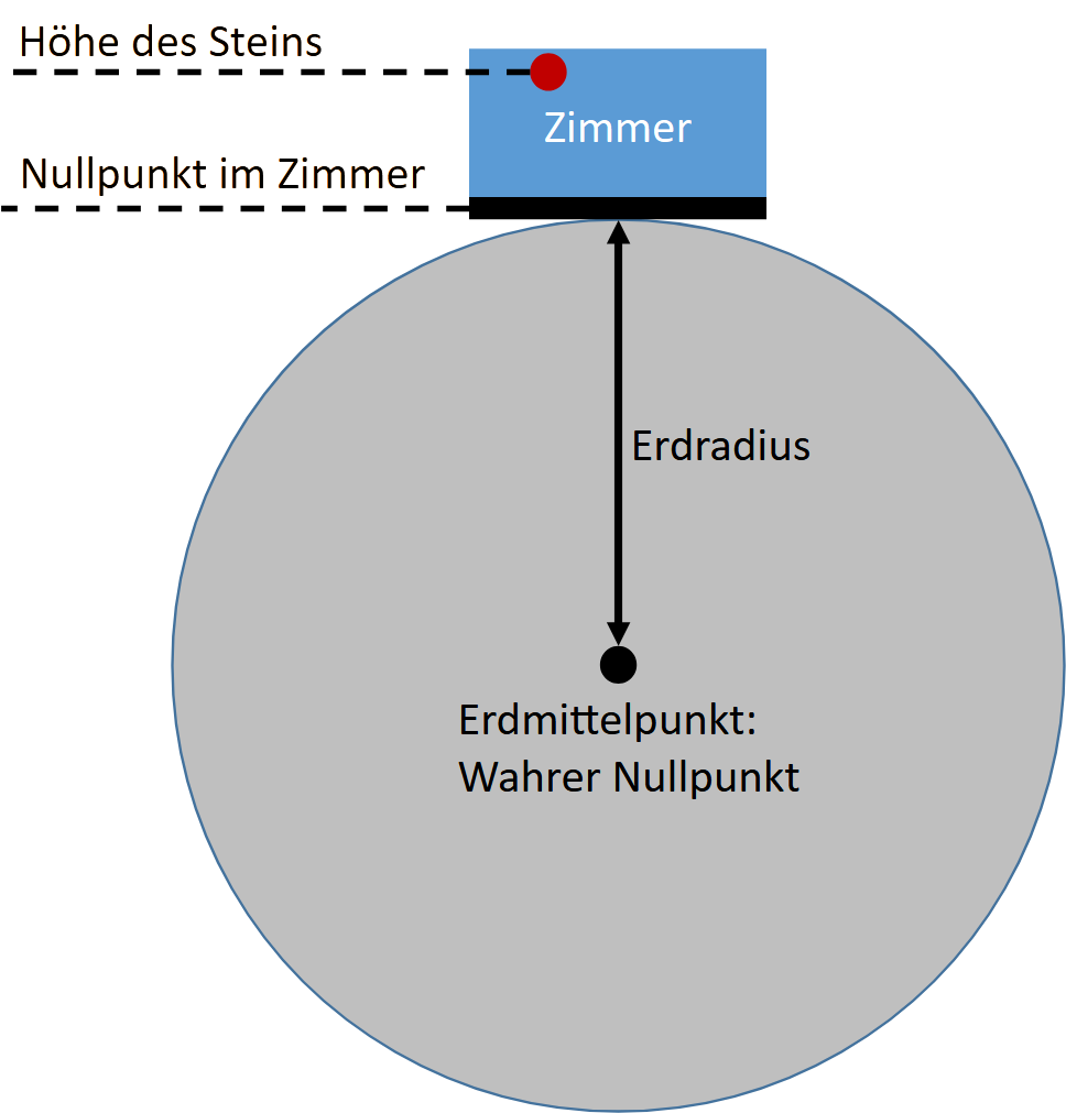
In electrical engineering we handle potentials in exactly the same way. There are always different potentials in a system, because all bodies carry different amounts of charge. Determining the charge is not easy to measure; we cannot count charges and therefore cannot determine potentials exactly. However, the potential difference, the voltage, can be measured very easily, and that is what we need to solve technical problems.
As with the height of the stone, the choice of the zero point does not matter as long as we are only interested in the difference Δh by which the stone has fallen. In electrical engineering we are no more interested in the potential of a body than in the absolute height of a stone above the centre of the Earth. We are only interested in the voltage between bodies. That is why we normally define the lowest potential as the zero point; then we can calculate more easily.
The value of the lowest potential is defined as φ = 0 V, just as we define the height of the floor in the room as h = 0 m. Both are physically wrong, but in both cases it does not matter, because above all we want to calculate easily. Just as we have to subtract the Earth's radius of r = 6371000 m from all other heights (I assume that this is the height of the floor), we subtract the value of the smallest potential, which we have chosen as the zero point, from all other potentials.
In the example above, we choose the smallest potential φ2 as the zero point and set φ2 = 0 V. Then the other potentials change to
The voltages are again calculated from the difference of the potentials in exactly the same way. Of course, the voltages are the same as before, because we have only subtracted the same amount from all potentials. This does not show up in the difference between two potentials.
In this system, however, the voltage U12 = φ1 – φ2, for example, can now be determined much more easily, because φ2 = 0 V and therefore U12 = φ1. In practice, many voltages in an electrical circuit are referred to the zero point. This zero point is so important that it gets its own circuit symbol and its own name: ground. More on this later.
Negative voltages
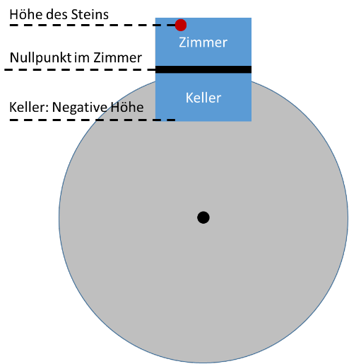
Just as there is a basement below the floor whose height is lower than that of the floor, there can also be potentials in circuits that are lower than the zero point. This is sometimes intended. We will come back to this later. What matters now: voltages can be positive and negative. The sign depends on whether the charge is greater or smaller than the charge of ground. Ground is the reference in the system that defines the zero point of the potentials.
Adding voltages
When batteries are connected one after the other, for example in a remote control, the voltages of the batteries add or subtract. For this, we have to connect the terminals in the right way. We can explain this with potential differences. Let us consider an Amazon remote control with two AAA batteries. Each AAA battery has a voltage of U = 1.5 V.
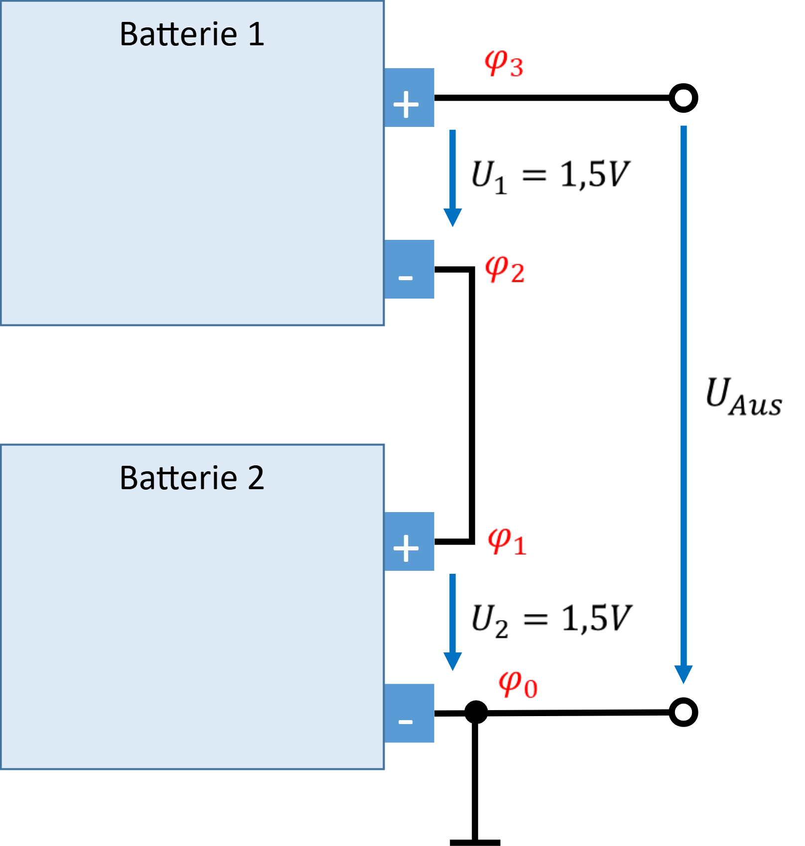
Drawn in black are cables or metal strips that electrically connect battery terminals in the remote control. The black circles are the points to which we can connect further parts of the circuit. The electronics of the remote control are connected to the right of the two points. The batteries only provide a voltage between the two points for operation.
We arbitrarily define the point with the lowest potential at the very bottom as the reference point or ground. So its potential is φ0 = 0 V. The lower battery raises the potential φ1 1.5 V above the potential φ0. So φ1 = 1.5 V.
The upper terminal of the lower battery is connected to the lower terminal of the upper battery. So the two terminals have the same potential. If these potentials were different, a charge balance would take place immediately until they were equal. So for electrically conductively connected bodies we can always assume that both have the same potential. Thus φ2 = φ1 = 1.5 V.
The upper battery raises the potential φ3 1.5 V above the value of φ2. So its potential is φ3 = φ2 + 1.5 V = 3 V. In the drawing, the output voltage is defined as the difference between the potentials φ3 and φ0. Thus for the output voltage UAus = φ3 – φ0 = 3 V – 0 V = 3 V. In this way we manage to supply the remote control with 3 V, even though we only have 1.5 V batteries. Here is the summary again:
Setting the reference point
Now we place ground between the two batteries and see what changes. We refer two new output voltages to ground.
Due to the new definition of ground, φ1 = φ2 = 0 V now applies. The lower battery pushes its two terminals 1.5 V apart. Because the upper terminal now has the value φ1 = 0 V by definition, φ0 = φ1 – 1.5 V = −1.5 V must apply. The potential φ0 is now negative (relative to φ1).
For the upper battery, it is still true that the battery raises φ3 1.5 V above φ2. Since φ2 = 0 V, φ3 = 1.5 V. The output voltage is usually referred to ground. We now get two output voltages, each drawn with the arrowhead at ground. UAus- = φ0 – φ1 = −1.5 V – 0 V = −1.5 V. And UAus+ = φ3 – φ2 = 1.5 V – 0 V = 1.5 V. Here is the summary again:
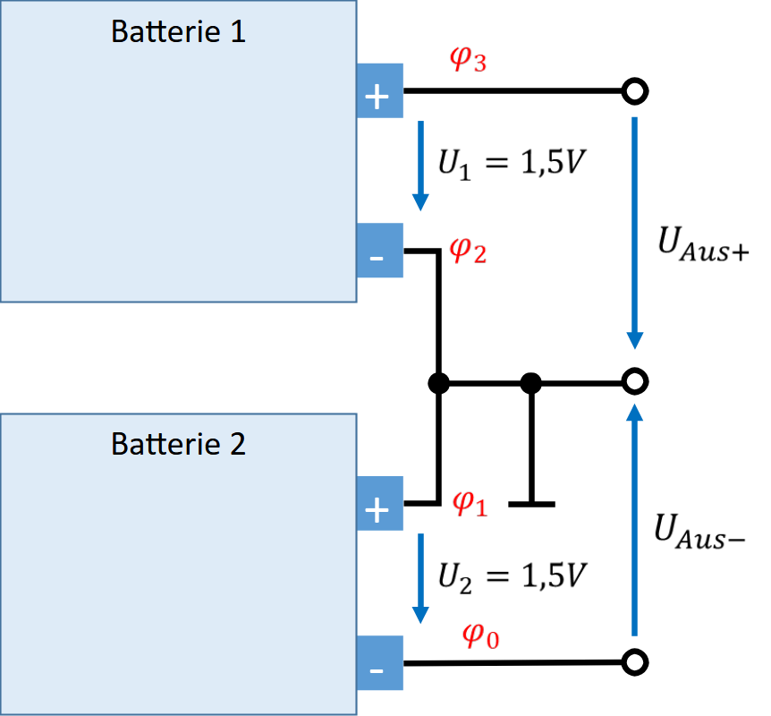
With the same batteries, we have created a positive and a negative voltage relative to ground. We obtain negative voltages by moving the zero point above the most negative potential.