Summary: Circuit Analysis
The following formulas were derived in the chapter on circuit analysis:
Series connection
Test: the conductor between two components contains no node.
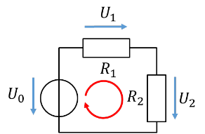
\[
\begin{gathered}
R_{\mathrm{Ges}} = \sum R_N\text{, here } R_{\mathrm{Ges}} = R_1 + R_2 \\[6pt]
\sum U_N = 0\,\mathrm{V} \text{ in the mesh, here } -U_0 + U_1 + U_2 = 0\,\mathrm{V} \\[6pt]
I_1 = I_2 = (\ldots) = I_N\text{, here } I_0 = I_1 = I_2 \\[10pt]
\text{Voltage divider of 2 resistors:} \\[4pt]
U_1 = U_0 \cdot \frac{R_1}{R_1 + R_2} \text{ or } U_2 = U_0 \cdot \frac{R_2}{R_1 + R_2}
\end{gathered}
\]
Parallel connection
Test: two components are directly connected to each other by conductors at both terminals.

\[
\begin{gathered}
\frac{1}{R_{\mathrm{Ges}}} = \sum \frac{1}{R_N} \\[6pt]
\text{2 resistors: } R_{\mathrm{Ges}} = \frac{R_1 \cdot R_2}{R_1 + R_2} \\[6pt]
\sum I_{\mathrm{in}} = \sum I_{\mathrm{out}}\text{, here } I_0 = I_1 + I_2 \\[6pt]
U_1 = U_2 = (\ldots) = U_N\text{, here } U_0 = U_1 = U_2 \\[10pt]
\text{Current divider of 2 resistors:} \\[4pt]
I_1 = I_0 \cdot \frac{R_2}{R_1 + R_2} \text{ or } I_2 = I_0 \cdot \frac{R_1}{R_1 + R_2}
\end{gathered}
\]