Learning Content and Theses

Platform for digital learning at HSHL

Networks with Resistors

Let us calculate current and voltage in an example network. For this, we take an AC voltage source and two resistors in series. The same calculation rules apply as for DC networks. We can apply the mesh rule, the node rule, the current divider and the voltage divider. Ohm's law also applies.

Only the peak values of voltages and currents change. The sine function always stays the same. The frequency and the phase do not change either. So for networks with resistors, we only calculate the peak values. As an example, we operate two resistors in series on a mains socket as the voltage source. The following calculation rules apply:

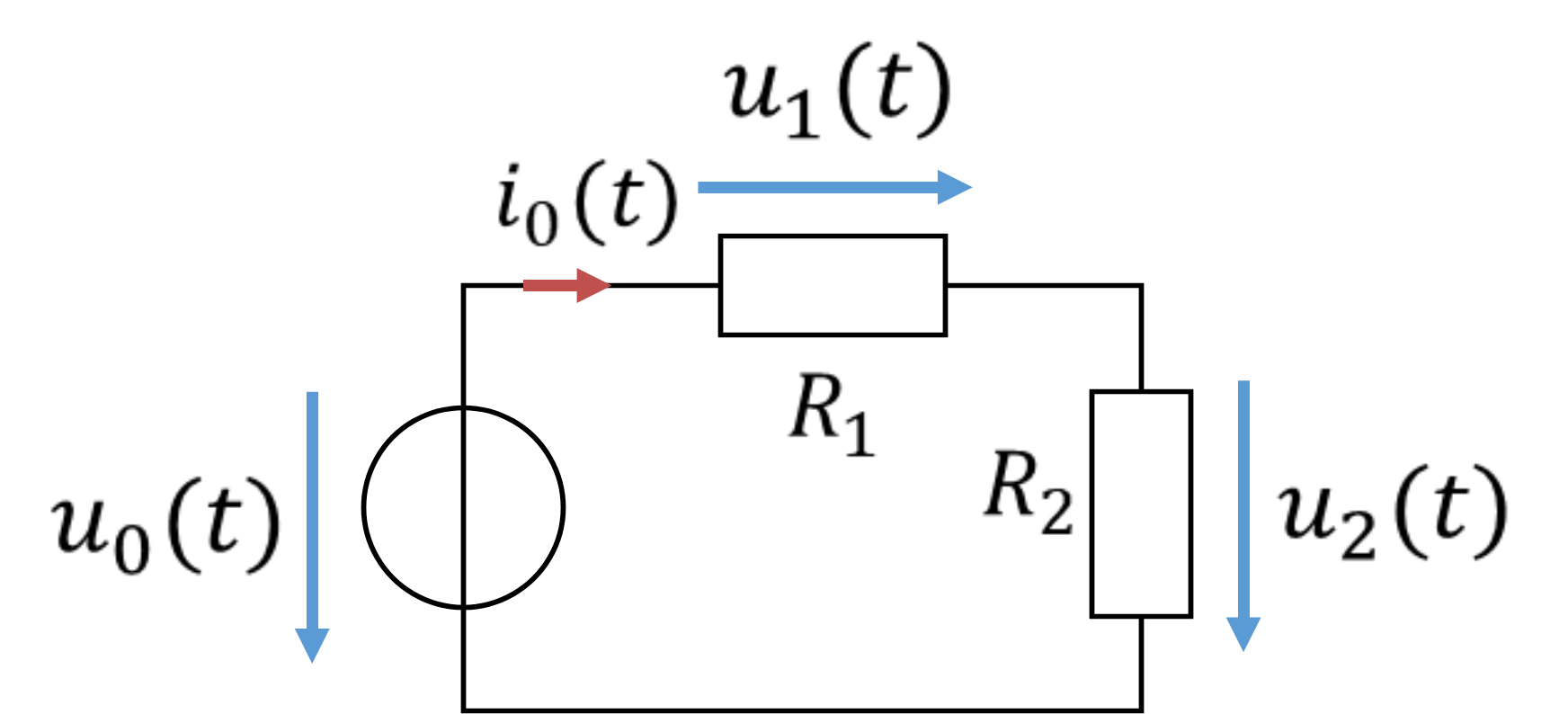
Voltage divider of R1 and R2 on the alternating voltage u0(t)
\[ \begin{gathered} R_1 = 1\,\mathrm{k\Omega};\ R_2 = 2\,\mathrm{k\Omega} \\[6pt] u_0(t) = 325\,\mathrm{V} \cdot \sin(\omega t) \text{ with } f = 50\,\mathrm{Hz} \rightarrow \omega = 2\pi f = 314\,\frac{1}{\mathrm{s}} \end{gathered} \]

Series connection:

\[ R_{\mathrm{Ges}} = R_1 + R_2 = 3\,\mathrm{k\Omega} \]

Source current:

\[ \hat{\imath}_0 = \frac{\hat{u}_0}{R_{\mathrm{Ges}}} = \frac{325\,\mathrm{V}}{3\,\mathrm{k\Omega}} = 108.3\,\mathrm{mA} \]

Ohm's law:

\[ \begin{gathered} \hat{u}_1 = R_1 \cdot \hat{\imath}_0 = 1\,\mathrm{k\Omega} \cdot 108.3\,\mathrm{mA} = 108.3\,\mathrm{V} \\[4pt] \hat{u}_2 = R_2 \cdot \hat{\imath}_0 = 2\,\mathrm{k\Omega} \cdot 108.3\,\mathrm{mA} = 216.7\,\mathrm{V} \end{gathered} \]

Voltage divider:

\[ \begin{gathered} \hat{u}_1 = \hat{u}_0 \cdot \frac{R_1}{R_1 + R_2} = 325\,\mathrm{V} \cdot \frac{1}{3} = 108.3\,\mathrm{V} \\[6pt] \hat{u}_2 = \hat{u}_0 \cdot \frac{R_2}{R_1 + R_2} = 325\,\mathrm{V} \cdot \frac{2}{3} = 216.7\,\mathrm{V} \end{gathered} \]

Mesh equation:

\[ \hat{u}_0 = \hat{u}_1 + \hat{u}_2 = 108.3\,\mathrm{V} + 216.7\,\mathrm{V} = 325\,\mathrm{V} \]

Node equation or current equation:

\[ \hat{\imath}_0 = \hat{\imath}_1 = \hat{\imath}_2 = 108.3\,\mathrm{mA} \]

You can see that all calculation rules from DC analysis also apply to alternating current – provided we only use resistors. Once we have calculated the peak values, we simply substitute them into the sine equation. Frequency and phase have not changed, so the following applies

\[ \begin{gathered} u_1(t) = \hat{u}_1 \cdot \sin(\omega t) = 108.3\,\mathrm{V} \cdot \sin(\omega t) \\[4pt] u_2(t) = \hat{u}_2 \cdot \sin(\omega t) = 216.7\,\mathrm{V} \cdot \sin(\omega t) \\[4pt] i_0(t) = \hat{\imath}_0 \cdot \sin(\omega t) = 108.3\,\mathrm{mA} \cdot \sin(\omega t) \end{gathered} \]

Simulation

With alternating voltage, we calculate networks of resistors exactly as with DC voltage. The sine is simply carried along in the calculation. You simply attach the sine to every voltage and every current. So every voltage and every current in this network is sinusoidal. Let us look at another similar example comparing direct current and alternating current:

Voltage divider with DC or AC voltage

\[ \begin{gathered} \text{DC voltage:} \\ U_0 = 10\,\mathrm{V},\ R_1 = 1\,\mathrm{k\Omega},\ R_2 = 1\,\mathrm{k\Omega} \end{gathered} \]
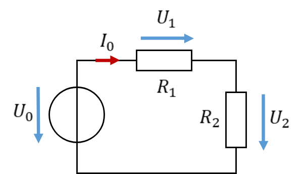
Voltage divider on DC voltage
\[ \begin{gathered} R_{\mathrm{Ges}} = R_1 + R_2 = 2\,\mathrm{k\Omega} \\[4pt] I_0 = \frac{U_0}{R_{\mathrm{Ges}}} = \frac{10\,\mathrm{V}}{2\,\mathrm{k\Omega}} = 5\,\mathrm{mA} \\[4pt] U_1 = R_1 \cdot I_0 = 5\,\mathrm{V} \\[4pt] U_2 = R_2 \cdot I_0 = 5\,\mathrm{V} \end{gathered} \]
\[ \begin{gathered} \text{AC voltage:} \\ u_0 = 10\,\mathrm{V} \cdot \sin(\omega t),\ R_1 = 1\,\mathrm{k\Omega},\ R_2 = 1\,\mathrm{k\Omega} \end{gathered} \]
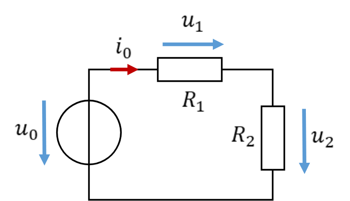
Voltage divider on AC voltage
\[ \begin{gathered} R_{\mathrm{Ges}} = R_1 + R_2 = 2\,\mathrm{k\Omega} \\[4pt] \hat{\imath}_0 = \frac{\hat{u}_0}{R_{\mathrm{Ges}}} = \frac{10\,\mathrm{V}}{2\,\mathrm{k\Omega}} = 5\,\mathrm{mA} \\ \rightarrow i_0(t) = 5\,\mathrm{mA} \cdot \sin(\omega t) \\[4pt] \hat{u}_1 = R_1 \cdot \hat{\imath}_0 = 5\,\mathrm{V} \rightarrow u_1(t) = 5\,\mathrm{V} \cdot \sin(\omega t) \\[4pt] \hat{u}_2 = R_2 \cdot \hat{\imath}_0 = 5\,\mathrm{V} \rightarrow u_2(t) = 5\,\mathrm{V} \cdot \sin(\omega t) \end{gathered} \]

What applies to voltage and current in a network of resistors with DC voltage applies to the peak values of voltage and current with AC voltage. In the voltage divider, the peak values are divided. All voltages and currents remain sinusoidal if the source voltage is sinusoidal. Resistors have no influence on the phases; the phase of the current and the partial voltages equals the phase of the source voltage.

So with the rules for DC networks, we can calculate all relevant parameters of AC quantities in resistor networks.

Split by degree programme

At this point, you can jump to the next chapter of your course via the menu. If you navigate with “Next”, you have to use a different link depending on your degree programme, because alternating current is taught differently depending on the degree programme.

For students of ISD and UFC, the treatment of alternating current ends here. ISD continues with measurement technology: Continue ISD
UFC continues with fields: Continue UFC

Students of ETR learn complex AC analysis under Continue ETR

BMT continues with simplified AC analysis under Continue BMT

Download course as PDF

The PDF contains all pages of the course. Interactive content is only available on the website.