General Control Loop
Important note: the results of this chapter only apply to systems without disturbances. In later chapters, these results are extended to systems with disturbances. Different formulas from those in this chapter are then used. So the following formulas are only valid if there is no disturbance in the system.
In the chapter before last, we used the similarity of all proportional systems to obtain a general mathematical description of this behaviour. We now only insert different values of kP for different systems and thus obtain the specific behaviour of our system.
We now apply this method of exploiting similarity to all control loops. First, let us look again at a general control loop. In the general control loop, function blocks and signals are given general names, without going into a concrete control application:
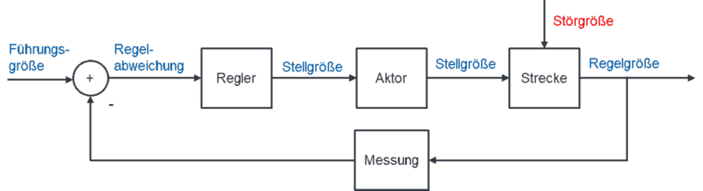
To arrive at a uniform, general solution for all possible control loops, the general control loop is first radically simplified.
Simplifying the measurement
First, we assume ideal measurement technology for measuring the controlled variable. It converts the physical quantity at the output of the system ideally and without error into a digital number. The digital number is used in the controller software. So the transfer function of the measurement is H = 1. In the cruise control, for example, only the quantity “analogue speed” is converted into the quantity “digital speed”.
What does H = 1 mean? The output quantity is then equal to the input quantity. If the transfer function = 1, we can also omit the block, because with H = 1 the block has no influence on the control loop. In the greatly simplified general control loop, we therefore connect the output of the system directly to the subtraction element.
Controller, actuator and plant
The function blocks controller, actuator and plant are connected in series. To simplify the structure, the transfer functions of function blocks connected in series can be combined into an overall transfer function by multiplying them. The following applies:
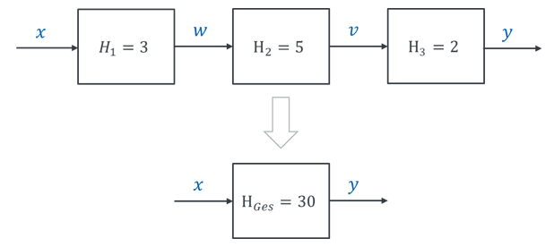
The function blocks “controller”, “actuator” and “plant” in the general control loop are combined into a single function block. We name the resulting block “A”. We can then calculate with a parameter A in the general solution. Only later do we assign a concrete system behaviour to A.
The combined block A thus consists of the controller, whose behaviour we can influence, and the actuator and plant, whose behaviour we cannot influence. Via the controller, we later have the possibility of influencing the behaviour of A.
The simplified general control loop looks like this:
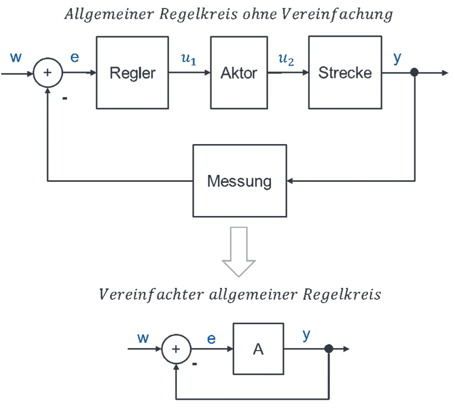
(Regler = controller, Aktor = actuator, Strecke = plant.)