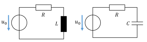
What waveform will the capacitor voltage have if the current is a sine? The current is integrated, and the integral of sine is “minus cosine”. The following applies:
What waveform will the inductor voltage have if the current is a sine? The current is differentiated, and the derivative of sine is cosine. The following applies:
If the current in the inductor is a sine, the voltage is a (positive) cosine.
Capacitor and inductor behave the same apart from the sign: they turn a sinusoidal current into a ± cosine voltage. A resistor turns a sinusoidal current into a sinusoidal voltage.
Addition and multiplication of resistance and reactance
For example, to calculate the total resistance in a series connection, we have to add resistances. In a parallel connection, we have to add and multiply. In DC networks, the following applies:
A reactance is added to another reactance “normally”. The reactance of an inductor counts as positive and that of a capacitor as negative.
\[ X_{\mathrm{Ges}} = X_L - X_C \]
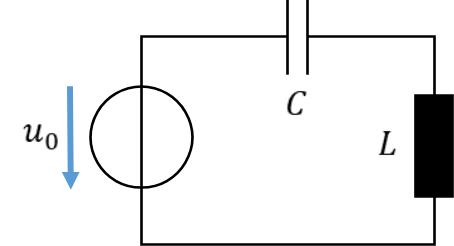
Reactances describe energy stores which, when integrating or differentiating, turn a sine into a cosine and vice versa. If a sinusoidal current flows through two reactances, the inductor turns it into a “plus cosine” voltage and the capacitor turns it into a “minus cosine” voltage. That is why the inductor reactance is added as positive and the capacitor reactance as negative.
Examples
First, we define a few components with which we then calculate by way of example.
\[
\begin{gathered}
\text{Resistor } R = 1\,\Omega \\[4pt]
\text{Inductor: } L = 6.36\,\mathrm{mH} \\[4pt]
\text{Capacitor: } C = 3.18\,\mathrm{mF} \\[4pt]
f = 50\,\mathrm{Hz} \rightarrow \omega = 2\pi f = 314\,\frac{1}{\mathrm{s}} \\[6pt]
X_L = \omega L = 314\,\frac{1}{\mathrm{s}} \cdot 6.36\,\mathrm{mH} = 2\,\Omega \\[6pt]
X_C = \frac{1}{\omega C} = \frac{1}{314\,\frac{1}{\mathrm{s}} \cdot 3.18\,\mathrm{mF}} = 1\,\Omega
\end{gathered}
\]
We define the reactance mainly so that we can calculate with alternating current almost as easily as with direct current. It is a mathematical simplification. However, it also describes the behaviour of the components with alternating current. A reactance is an AC resistance. It indicates how much resistance a component offers to alternating current. With a larger reactance, less current flows.