Frequency Dependence
The impedance of energy stores depends on the angular frequency ω. What does this mean for voltage and current in networks with energy stores?
Inductor
For the inductor, the impedance increases with frequency. So the current through an inductor on an AC voltage source decreases as the frequency of the voltage increases. For very high frequencies, the following applies to the impedance of an inductor:
At very high frequencies, an inductor is modelled as an open switch. A component with infinitely high impedance blocks any flow of current. No current at all flows through the branch containing the inductor. All components in series with the inductor have no effect in the circuit. They can also be omitted when calculating voltage and current without falsifying the results.
At very low frequency – e.g. direct current with f = 0 Hz – the following applies to the inductor:
An inductor has no resistance with direct current. It is modelled as an ideal conductor. After all, it only consists of a wire wound around a magnetic core. With direct current, only the wire resistance remains, which we approximate as R = 0 Ω to a first approximation.
With direct current, the current through the inductor is usually determined by the other components in the network. If only an inductor is connected to an ideal DC voltage source, the current through the inductor is infinitely large. This is of course not possible in practice; it is only a thought experiment.
Capacitor
The capacitor always behaves reciprocally to the inductor. Its impedance is proportional to 1/ω. At very high frequencies, the following applies
At high frequencies, the capacitor is modelled as an ideal conductor. With direct current at f = 0 Hz, it is modelled as an open switch. The consequences in the circuit are the same as those described for the inductor in these cases.
For the cases f → ∞ and f = 0 Hz, we can simplify circuits by modelling energy stores either as ideal conductors or as open switches. The following circuit is simplified as an example:
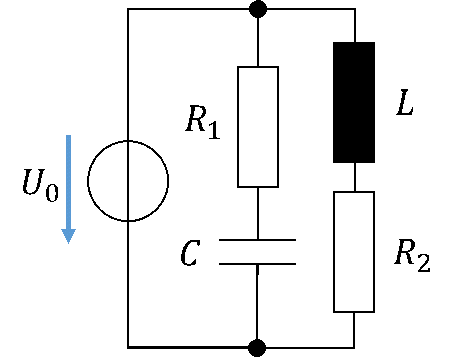
For f → ∞, the capacitor is an ideal conductor and the inductor is an open switch. So no current flows through L and R2. At very high frequencies, only R1 is effective in the circuit. To calculate voltages and currents, we can simplify the circuit as follows:
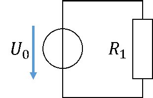
The other components have not disappeared at f → ∞. They simply have no effect. We only use the simplified equivalent circuit above to calculate voltages and currents more easily. No current flows through the inductor and R2. There is also no voltage across these components, because the inductor, acting as an open switch, disconnects them from the source. The same current flows through the capacitor as through R1. No voltage drops across it, because its impedance is 0 Ω.
For f = 0 Hz (DC voltage), the capacitor is an open switch and the inductor is an ideal conductor. So no current flows through C and R1. At f = 0 Hz, only R2 is effective in the circuit.
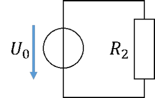
The inductor current equals the current through R2. The capacitor disconnects itself and R1 from the source, so that no current flows through these components and no voltage is present across them.
Even if the frequency does not take the extreme values 0 and infinity, this consideration is helpful. It shows that energy stores in circuits are only effective within a certain frequency range. Outside this range, their AC resistance (impedance) is much smaller or much larger than that of all other components in the circuit.
You can compare this with a series connection of an extremely large resistor and an extremely small resistor. The small resistor has practically no influence on the voltage and current in the circuit. Here is an example:
To calculate voltage and current, you can simply ignore R2. In practice, this does not cause any error in the calculation and design of a circuit.