Simplifying Circuits
A real circuit generally consists of series and parallel connections of many components. Following the rules just worked out, these can be combined further and further step by step. Combining all components of a circuit is used, for example, to determine the current load on a voltage source.
Load on a source
When you select a battery to supply a circuit, the manufacturer specifies in the data sheet a maximum current that can be drawn from the battery. Evidently, a car battery with a volume of several litres can deliver more current than a small button cell in a wristwatch. The current consumption of the circuit – i.e. the current that flows from the battery into the circuit – must therefore match the battery.
It is mathematically not easy to determine the current consumption of a complex circuit. If the circuit is reduced to, at best, a single equivalent resistor, the calculation is easy.
This is shown using the example of the following circuit, which is to operate several loads, all modelled as ohmic resistors. The following applies
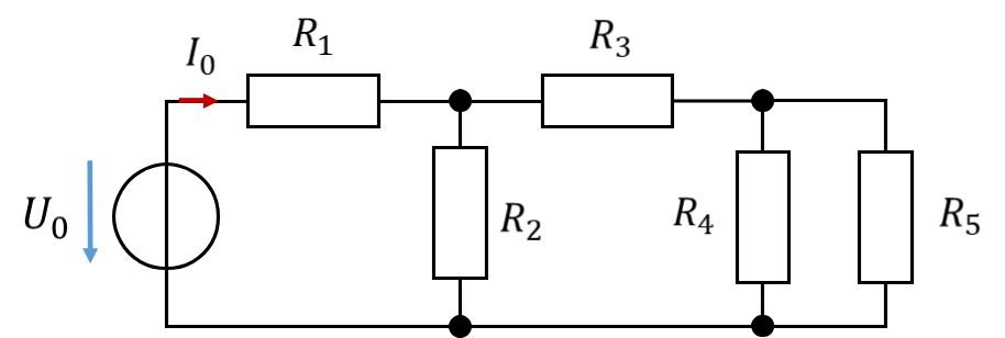
To calculate the load on the voltage source with the current I0, the circuit is simplified step by step without changing the voltage and current at the source.
In the first step, R4 and R5, which are connected in parallel, are combined into one resistor. This results in the following simplified circuit:
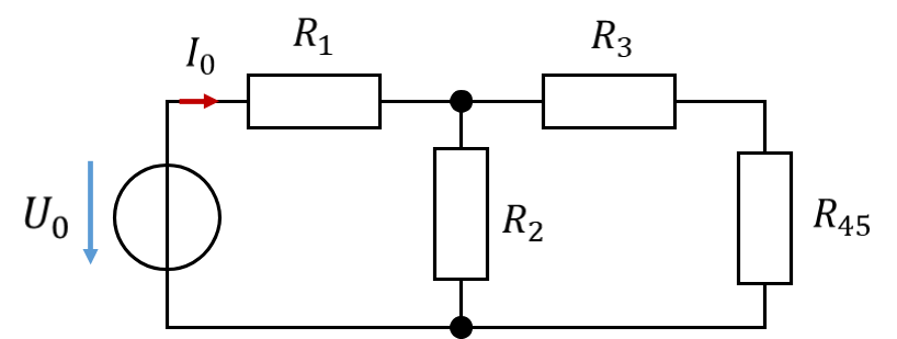
In the second step, the series connection of R3 and R45 is combined:
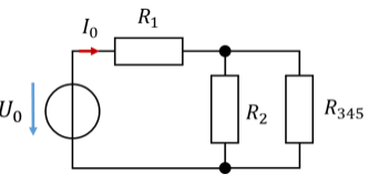
Now R2 and R345 are in parallel. In a further simplification step, the following applies:
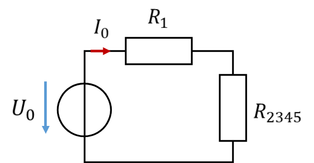
Finally, the series connection of R1 and R2345 is combined into a total resistance.
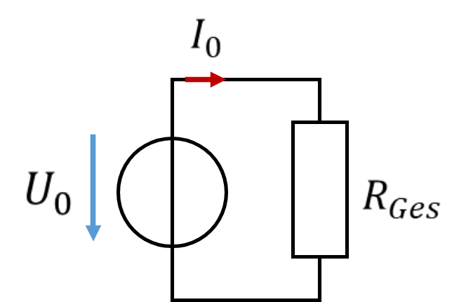
The current loading the source can now easily be calculated as
This current flows from the battery into the circuit. With this value, the battery can now be selected.
Calculating partial voltages and partial currents
The different simplification steps can be used backwards to calculate partial currents and partial voltages in a network more easily. For this purpose, the partial voltage U2 across R2 and the partial current I3 flowing through R3 are calculated in the example above.
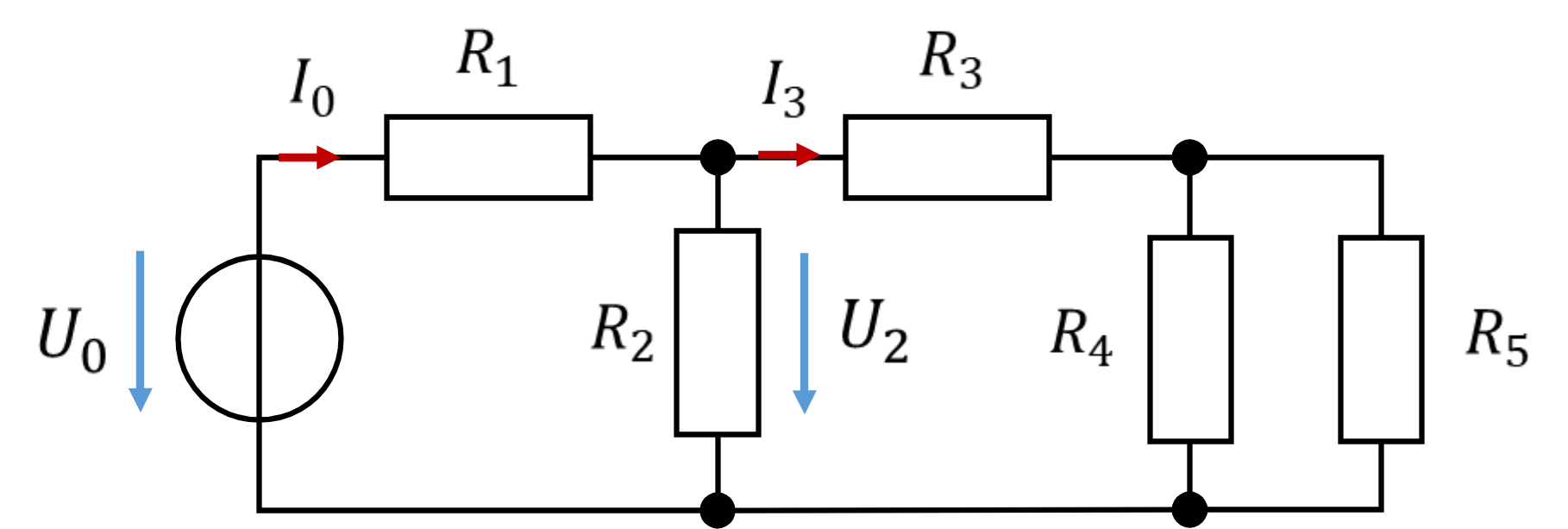
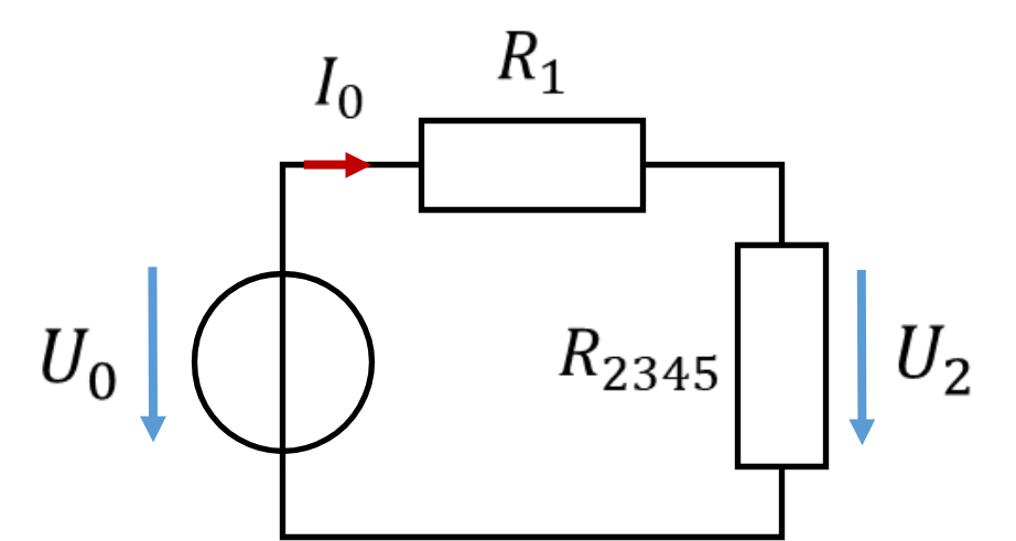
The voltage U2 equals the potential difference between the nodes above and below the resistor R2. So U2 is present across the equivalent resistor R2345 in the second-to-last simplification step of the circuit.
The current I0 = 0.5 A flows through R2345. According to Ohm's law, the following voltage drops across this resistor:
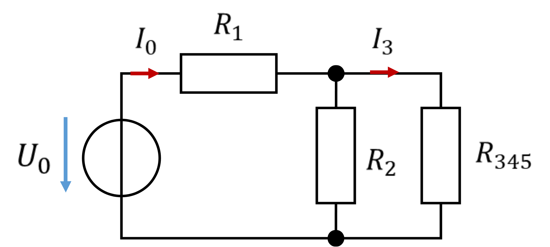
The current I3 can be calculated relatively easily using a current divider in the third simplification step, because this current flows through the equivalent resistor R345: