Transfer Function of an ADC
The range of numbers that an ADC can output is determined by its number of bits. A bit is the smallest digital unit. It can take the values 0 and 1. In an 8-bit number, each bit is given the following meaning.
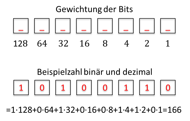
So the binary number 10100110 has the decimal value 166.
If all bits have the value 0, the decimal number is 0. If all bits have the value 1, the decimal number for 8 bits is 255. An 8-bit binary number with n = 8 can take 2n = 28 = 256 different values. Since 0 is one of the numbers, the maximum number is:
An 8-bit ADC converts the input voltage into an 8-bit binary number with a decimal number range of Zahl (number) = [0 .. 255]. I describe ranges of values in square brackets, containing first the smallest and then the largest number of the range. A 12-bit ADC has a number range of Zahl = [0 .. 212 – 1] = [0 .. 4095]. With this formula, you can determine the range of the number at the output of an ADC for any number of bits.
Every ADC needs a reference voltage UREF. The input voltage is compared with the reference voltage. In many ADCs, the reference voltage is specified internally; in some, you have to connect it yourself to a pin of the IC. A voltage at the input of the ADC within the range UADC = [0 V .. UREF] is mapped proportionally onto the value of the number at the output. This means that the input voltage UEIN,ADC = 0 V produces the value Zahl = 0 at the output. The voltage UEIN,ADC = UREF produces the maximum number at the output, Zahl = 255 for an 8-bit ADC. Intermediate values are calculated with the formula
Since an ADC always outputs integers, we have to round up or down. The formula above only applies if the input voltage lies within the input voltage range of the ADC, i.e. for 0 V ≤ UEin ≤ URef.
If the input voltage is less than 0 V, the ADC always outputs Zahl = 0. If it is greater than UREF, it always outputs Zahl = 2n – 1. So the characteristic of an ADC is proportional within its meaningful input voltage range and, outside this range, not strictly monotonic and therefore unusable. The following characteristic results for a 3-bit converter with a reference voltage of UREF = 3 V:
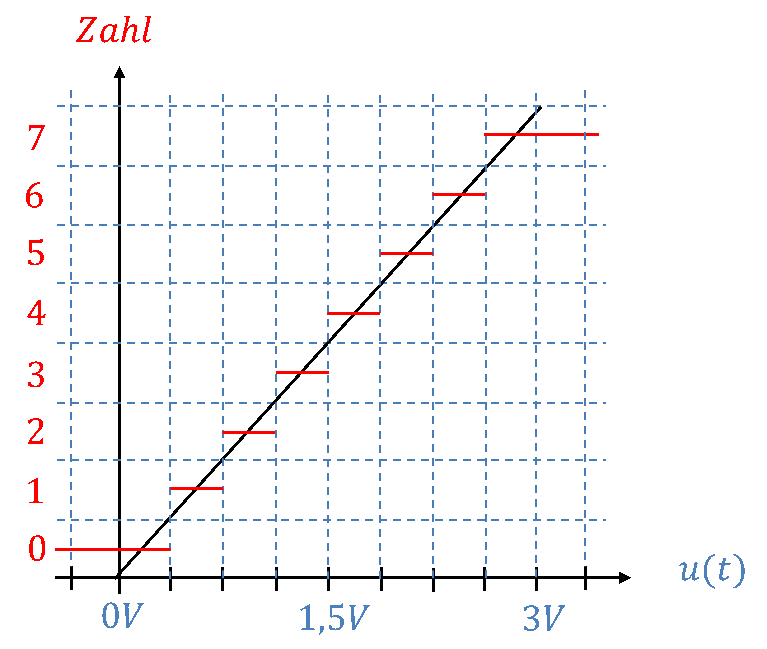
Each voltage is assigned a number that depends on between which vertical dashed lines the voltage lies. If the voltage lies between 1.5 V and 1.875 V, the number 4 is output. If the voltage is greater than 2.625 V, the value 7 is output. If the voltage is less than 0.375 V, a 0 is output. The ideal characteristic is shown in black, the real sections of the real characteristic in red.
If the number of bits n is large enough, the staircase shape of the characteristic is no longer noticeable in practice. You can calculate as if the characteristic were a straight line. By rounding the numbers up or down, you get the “real” value that the ADC outputs as the result.