Buffer Amplifier
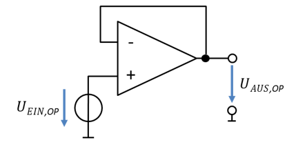
The buffer amplifier, or “buffer”, amplifies a signal by a factor of 1. So it does not change the input signal at all; it simply passes it on to the output. You need the buffer for decoupling circuit sections, which is explained a few chapters later. You get to know it here so that you can use it later. A buffer is based on the non-inverting op-amp. The following circuit implements a buffer:
\[
\begin{gathered}
\text{Non-inverting op-amp:} \\[6pt]
U_{\mathrm{Aus,OP}} = \left(1 + \frac{R_2}{R_1}\right) \cdot U_{\mathrm{Ein,OP}} \\[6pt]
H = \frac{U_{\mathrm{Aus,OP}}}{U_{\mathrm{Ein,OP}}} = 1 + \frac{R_2}{R_1} \\[6pt]
\text{For the buffer: } R_2 = 0\,\Omega \text{ and } R_1 \rightarrow \infty \\[6pt]
H_{\mathrm{Buffer}} = 1 + \frac{0\,\Omega}{\infty} = 1 \\[6pt]
U_{\mathrm{Aus,OP}} = H \cdot U_{\mathrm{Ein,OP}} = U_{\mathrm{Ein,OP}}
\end{gathered}
\]
This circuit is always used when no current may flow out of the sensor circuit, because no current flows into the non-inverting input of the op-amp. Otherwise it does nothing.