Real Voltage Source
The behaviour of a real voltage source can be illustrated using the example of a car battery. Suppose the battery is charged to 12 V. If you have switched on the car's headlights and start the engine, you will see that the light becomes somewhat dimmer during starting. The engine's starter is an electrical load that turns the combustion engine until it runs by itself. The headlights are also electrical loads. Both are connected to the battery.
Starting the engine draws so much current from the battery that the battery voltage drops. You can tell that the battery voltage drops because the headlights shine more dimly, since they receive less voltage. The voltage of a battery depends on the current drawn from it. So the battery is not an ideal voltage source. Without a load, no current flows from the battery. Then the voltage is 12 V. As soon as current flows, the voltage drops from this initial value.
We model this behaviour with a series connection of an ideal voltage source and an “internal resistance”. The internal resistance makes the voltage at the battery terminals drop as soon as current flows. It is part of the battery and is therefore located before the terminals. In this way, we reproduce a real battery with known ideal components so that we can calculate its real behaviour. The model looks like this:
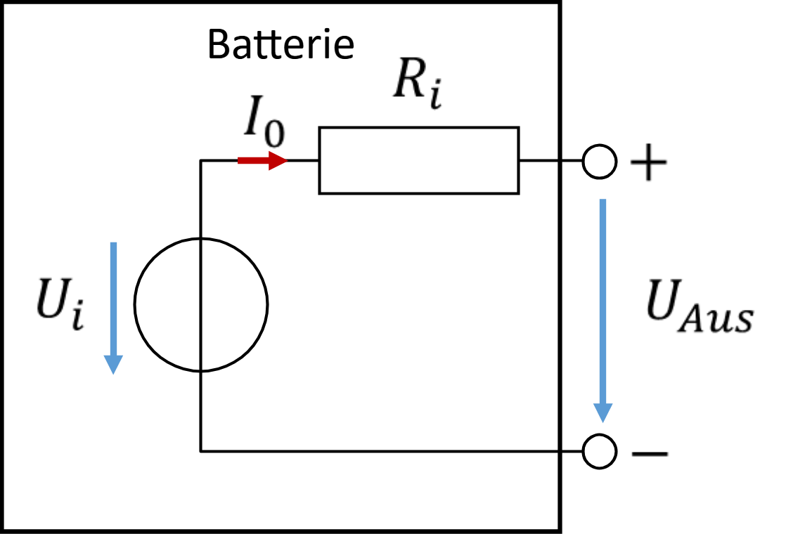
The terminals are marked + and –. The voltage that can be measured at the battery from outside is called UAus (output voltage). For a calculation, we need the model parameters Ui and Ri.
Determining the model parameters
Let us use operating points that are as simple as possible. An operating point is a state in which a circuit is operated. In the simplest operating point, no current flows out of the circuit because it is not loaded. So no current flows through the internal resistance. The output voltage therefore equals the internal voltage. We call this operating point “open circuit”.
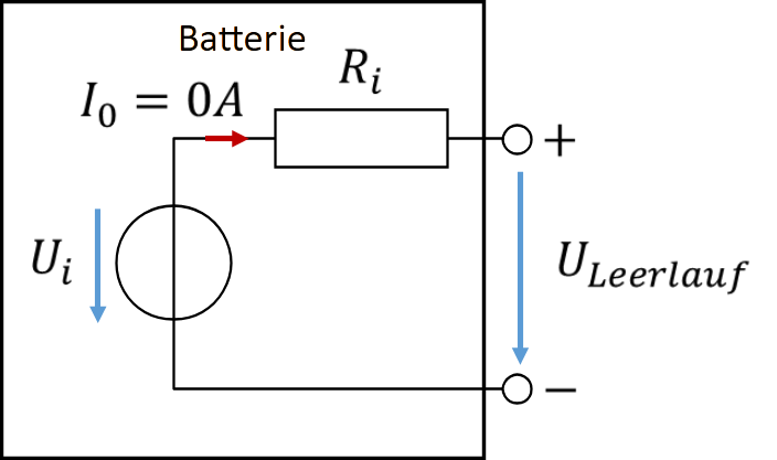
The open-circuit voltage ULeerlauf equals the voltage of the internal ideal voltage source. It can be measured very easily by measuring the voltage of an unloaded battery.
In the next operating point, we set the output voltage to 0 V by a short circuit. To do this, we place an ideal conductor (i.e. a wire) between the output terminals of the battery. We then measure the current through this conductor. For this you use, for example, a multimeter. You will get to know this in the lab course. In the short circuit, the circuit looks like this:
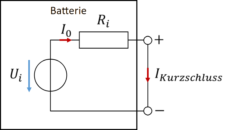
We calculate the internal resistance as the open-circuit voltage divided by the short-circuit current IKurzschluss. This is the “official” method for determining the model parameters in electrical engineering. In practice, it is difficult to apply, because the short-circuit current can be very high. If you short-circuit a LiPo battery from your smartphone, for example, the current is so high that the battery starts to burn. If you short-circuit the voltage at a mains socket, the fuse blows immediately.
If we have two pairs of values of voltage and current, we can use them to calculate two model parameters. We keep the open circuit, since it is so nice and easy to establish. Then we only need one more pair of voltage and current. To get it, we load the real source with a load resistor. Its resistance should be as low as possible, but large enough that the source is not destroyed.
The circuit then looks like this:
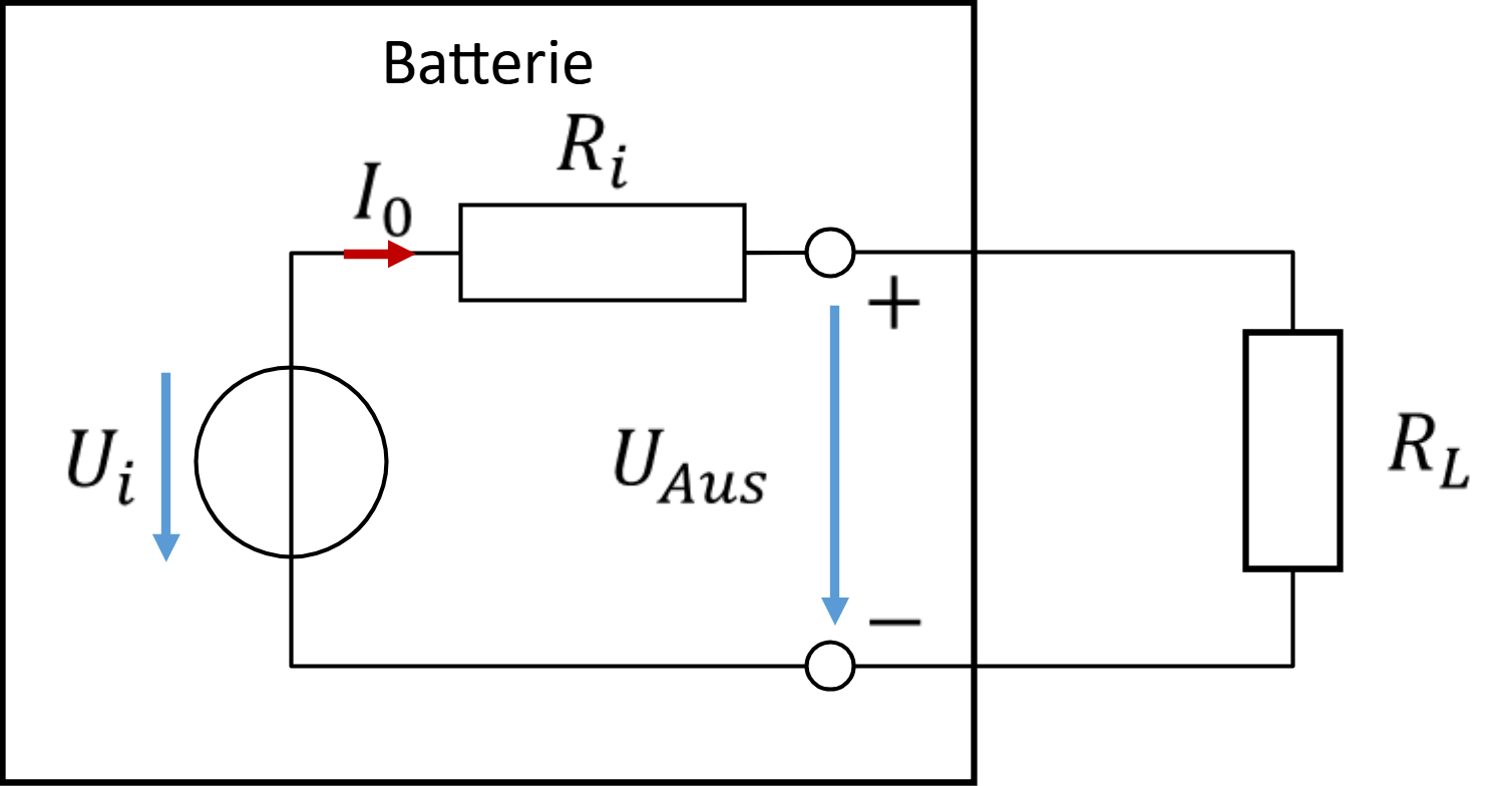
We measure the voltage and current at the load resistor with a multimeter. Then we look at the equations for the series connection:
The quantity Ui is known from the open-circuit measurement. We measure the output voltage and current with a multimeter. This allows us to calculate the value of Ri.
Example: if no current flows from the car battery, the voltage at the terminals of a car battery is UAus = 12 V. If a load draws 10 A from the battery, the output voltage drops to 11 V. This allows us to determine the model parameters.
Real batteries
A real battery differs from the ideal voltage source in further ways: the available separated charge is limited. This is described by the capacity C of the battery, which is usually given in [C] = Ah. A battery with C = 1500 mAh can, for example, supply a current of I = 1500 mA for one hour; then it is empty.
A real battery can only be loaded with a limited maximum output current. The maximum output current is usually given as
If this battery is advertised with a discharge current of 20C, this means:
These two effects are not taken into account in the model. As an example, the following battery is considered.
Characteristics:
- Open-circuit voltage Ui = 3.7 V
- Capacity C = 600 mAh
- Continuous load capacity (maximum current) IMax = 20C = 12 A
- Internal resistance (empirical value, not from the manufacturer's specification): Ri = 15 mΩ
The output voltage thus depends on the open-circuit voltage, the internal resistance and the output current. This particular battery is modelled as follows:
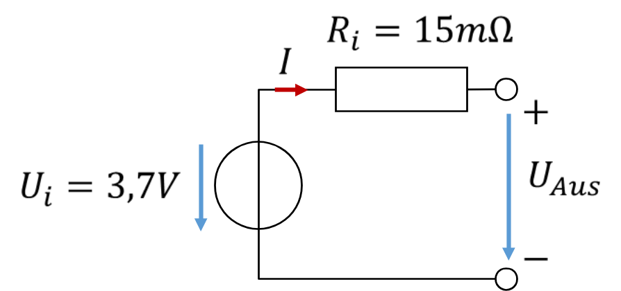
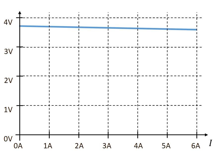
In the figure above, you see the model of the battery. In electrical engineering, we also speak of an electrical equivalent circuit. Below it, you see the formula for the output voltage. Below that, it is shown graphically versus the output current. The internal resistance is low, so the output voltage drops only slightly with the current.