Laboratory Power Supply
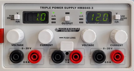
A laboratory power supply is used to provide adjustable voltages in the lab. The laboratory power supply behaves almost like an ideal voltage source. The power supply in our electrical engineering lab has three voltage outputs. Each output has a black and a red socket. The potential of the red socket is always above that of the black socket. The "Voltage" knob sets the value of the voltage between the red and the black socket. The "Current" knob sets the maximum output current – more on this later. The voltages on the left and right channels are adjustable. The green LCD display shows that, in the example below, the left channel is set to 1 V and the right channel to 12 V output voltage. The middle channel is permanently preset to 5 V.
The voltage can only be measured at the sockets once the middle "OUTPUT" button has been pressed. The LED above this button lights up green as soon as the voltage is active. So you do not need to switch off the power supply to deactivate the voltage.
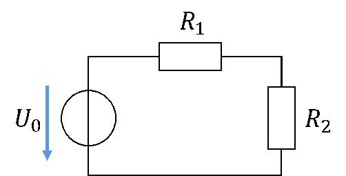
When a circuit consisting of two resistors is operated from a voltage source, we use the following circuit diagram:
You realise the voltage source with a laboratory power supply as follows:
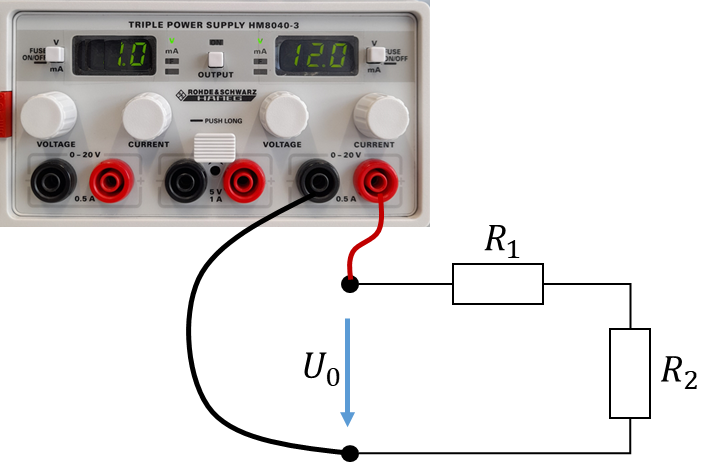
Now a voltage of 12 V is applied to the inputs of the circuit.