Learning Content and Theses

Platform for digital learning at HSHL

Current-to-Voltage Converter

Some sensors provide a current as their electrical output quantity. One example is the photodiode, which outputs a current that depends on the light. In biology there are processes that emit light, and its intensity can be measured with photodiodes. We are looking for a solution that converts a current into a suitable voltage for the ADC in the analogue signal processing. This is done by the current-to-voltage converter, also called a transimpedance amplifier (TIA). I will use this abbreviation from now on.

The TIA is based on the inverting amplifier.
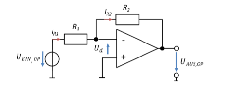
Inverting amplifier with currents I_R1 and I_R2
\[ \begin{gathered} \text{Mesh with the input voltage:} \\[6pt] -U_{\mathrm{Ein,OP}} + U_{R1} - U_d = 0\,\mathrm{V} \rightarrow U_{R1} = U_{\mathrm{Ein,OP}} \text{ with } U_d = 0\,\mathrm{V} \\[6pt] \text{At resistor } R_1\text{: } I_{R1} = \frac{U_{R1}}{R_1} = \frac{U_{\mathrm{Ein,OP}}}{R_1} \\[6pt] \text{Node equation: } I_{R2} = I_{R1}\text{, no current flows into the op-amp} \\[6pt] \text{At resistor } R_2\text{: } U_{R2} = R_2 \cdot I_{R2} \\[6pt] \text{Mesh with the output voltage:} \\[6pt] U_d + U_{R2} + U_{\mathrm{Aus,OP}} = 0\,\mathrm{V} \rightarrow U_{\mathrm{Aus,OP}} = -U_{R2} \text{ with } U_d = 0\,\mathrm{V} \\[6pt] U_{\mathrm{Aus,OP}} = -U_{R2} = -R_2 \cdot I_{R2} = -R_2 \cdot I_{R1} = -\frac{R_2}{R_1} \cdot U_{\mathrm{Ein,OP}} \\[6pt] \text{Key equation for the TIA: } U_{\mathrm{Aus,OP}} = -R_2 \cdot I_{R1} \end{gathered} \]

The inverting amplifier outputs the current in the input mesh multiplied by R2. If a sensor feeds this current directly into the node between R1 and R2, the output voltage of the op-amp is already proportional to the input current. A circuit for this looks as follows:
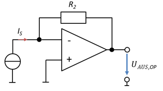
Current-to-voltage converter (TIA): current source I_S at the minus input, feedback via R_2
\[ \begin{gathered} U_{\mathrm{Aus,OP}} = -R_2 \cdot I_S \\[6pt] H = \frac{U_{\mathrm{Aus,OP}}}{I_S} = -R_2 \end{gathered} \]

The sensor current is modelled as an ideal current source. So you connect a photodiode directly to the op-amp input.

A real sensor is always a real current source. It therefore has an output resistance. So let us change the model of the sensor in the circuit:
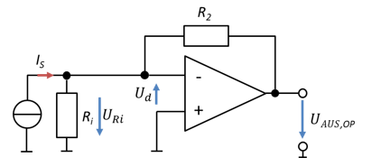
Current-to-voltage converter with internal resistance R_i of the current source
\[ \begin{gathered} \text{Mesh with the current source:} \\[6pt] -U_{Ri} - U_d = 0\,\mathrm{V} \rightarrow U_{Ri} = 0\,\mathrm{V} \text{ with } U_d = 0\,\mathrm{V} \end{gathered} \]

The voltage Ud between the two op-amp inputs is always 0 V. The current source and its internal resistance are in parallel with the voltage Ud. So there is no voltage across either the current source or the internal resistance. The current through the internal resistance – which would actually falsify the measurement – is always 0 in this circuit. That is why it is popular for current measurement.

Download course as PDF

The PDF contains all pages of the course. Interactive content is only available on the website.