Instrumentation Amplifier
The instrumentation amplifier is a circuit consisting of several op-amps. These are usually combined in one IC package, so you do not notice any of this. Just like the differential amplifier, the instrumentation amplifier amplifies a voltage difference. Its circuit is not based on amplifier structures you know. It is set with a single resistor. Unfortunately, there is no uniform formula for the gain; it varies from manufacturer to manufacturer and must be taken from the data sheet.
The input signals (modelled here as voltage sources) are connected directly to its two inputs. The resistors for the circuit are already integrated in the amplifier. That is why they are not shown in the circuit diagram.
The instrumentation amplifier has two additional inputs for the gain resistor. This is the only component we need in addition to the amplifier. The instrumentation amplifier is modelled as follows:
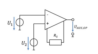
The voltage at the non-inverting input (+) minus the voltage at the inverting input (−) is always calculated. The gain G is used in the data sheet instead of the “v” we have used so far. For a particular instrumentation amplifier, the gain is, for example:
Why do we need the instrumentation amplifier if the differential amplifier can already amplify a voltage difference? The instrumentation amplifier draws no input current at its inputs. So no current is drawn from the sensor circuit. More on this in the following chapter.