Offset in Signals
Let us return to the example of the PT100 operated on the current source. We want to condition the sensor voltage for an ADC whose reference voltage is 3 V. Let us look at the gain that is necessary or possible:
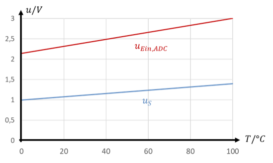
If the offset of UOFFSET = 1 V is first subtracted from this signal, the following applies:
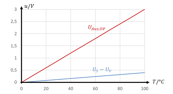
The red signal shows the input voltage of the ADC at the output of the op-amp circuit in each case. With the signal that is first shifted and then amplified, the input voltage range of the ADC is used much better. The characteristic is then proportional, because it no longer has an offset.
The sensitivity of a characteristic equals its slope. It indicates how strongly the output quantity changes when the input quantity changes. With a high sensitivity, the output quantity changes strongly even if the input quantity changes only minimally. This is the behaviour we need after a sensor. For the sensitivity of the two solutions at the ADC input, the following applies:
So it is advantageous to shift the sensor voltage first and only then amplify it if it has an offset. The advantage is all the greater, the larger the offset is relative to the “useful component” of the sensor voltage. The useful component is the part of the voltage that is influenced by the physical quantity.
Let us look at another example that shows the advantages of shifting the sensor signal:
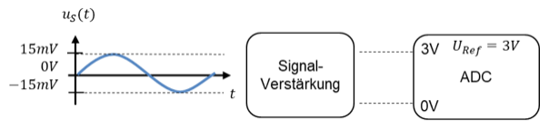
To amplify the peak value of the sensor voltage of 15 mV to the ADC reference voltage of 3 V, we need a factor v = 200. However, this amplifies the smallest sensor voltage of −15 mV to −3 V. This problem can only be solved by shifting the signal first and only then amplifying it. If the signal is first shifted upwards by 15 mV, the following applies:
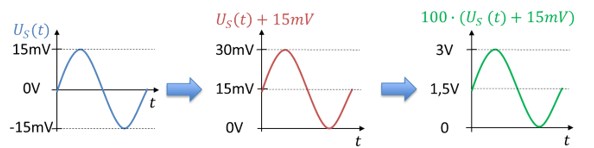
It is not individual voltage values that are shifted and amplified, but ranges of voltage. A measurement system specifies a measuring range in the physical quantity. A pressure sensor, for example, measures the pressure in the range P = [0 .. 20 bar]. This results in a sensor voltage that lies within a range of values, i.e. it does not just take a fixed numerical value. The AD converter accepts voltages within the range [0 V … URef] at its input. We have to look at how such ranges are converted.
Calculating with ranges of values
If a “shift value” is added to a range of values, this addition acts on all values, including the limits of the range. In linear systems, it is sufficient to consider only the limits of the ranges. The following applies:
If a range of values is multiplied by a factor, all values within the range are multiplied by the factor, including the limits of the range. The following applies
The art lies in finding the right shift value and the right factor. I will show this with the following example:
Approach 1
We first shift the sensor voltage into the range [0 V … 20 mV]. To do this, we add the shift voltage UV = 10 mV. The following applies
Next, we look for the appropriate gain value to adapt the shifted sensor voltage to the input voltage of the ADC. Whenever one of the range limits is 0, this calculation is easy. No matter what factor you multiply 0 by, the result is always 0. So the sensor voltage 0 V is always mapped to the ADC voltage 0 V. You only have to consider the other limit. By what factor must the 20 mV be amplified to give 3 V? For this, we use the formula
Approach 2
In a new problem, we shift the sensor voltage into the range [−20 mV … 0 V]. To do this, we add the shift voltage UV = −10 mV. The following applies
Next, we look for the appropriate gain value to adapt the shifted sensor voltage to the input voltage of the ADC. By what factor must the −20 mV be amplified to give 3 V? For this, we use the formula
As you can see, we cannot solve the problem with one general formula. You have to think about which limit of the sensor voltage is to be mapped to which limit of the ADC voltage. The following subchapters present three circuits for solving this problem.
Offset and transfer function
If a function block contains an offset in its internal signal processing, the transfer function causes problems.
A transfer function should always be independent of the input quantity. If, for example, the transfer function is constant over the input quantity, it is evidently independent of it. Because the transfer function H corresponds to the slope m of the characteristic of a straight line, a constant transfer function leads to a constant slope of the characteristic. For every linear function, the slope m is constant. For simplicity, in this tutorial we only consider linear transfer functions.
What happens with function blocks with linear behaviour of the form y = m ∙ x + b? They have an offset of size b. The characteristic is shifted upwards by b. So the behaviour is linear, but not proportional. As an example of a non-proportional function block, we look at the temperature sensor “PT100”, which is often used in this tutorial. Its behaviour is described as:
But the transfer function of the PT100 consists of two terms. If only the second term came out here, the transfer function would be helpful, because the second term is the slope of the characteristic. The first term, 100 Ω / T, is a real nuisance. Here the slope evidently does not correspond to the complete transfer function, but only to part of it.
In general, linear behaviour with an offset no longer readily allows the transfer function H = y / x to be set up. H is then no longer a constant. This is mathematically possible, but it does not help. The purpose of the transfer function is that we can combine the transfer functions of function blocks connected in series. But this only applies to proportional functions without a shift b.
For a linear system, it is helpful to subtract the parameter b first. This turns the linear function into a proportional function. The following applies:
If we manage to subtract the value 100 Ω from the value of the PT100, we obtain a change in resistance that is proportional to the temperature. Then we can amplify the signal normally afterwards. This part of the tutorial is about exactly this: how can we first shift a signal (add or subtract) and then amplify it (multiply)?