Parallel Connection
Two components are connected in parallel if there are no other components between the terminals that connect them. If you mentally sit on one terminal of a component, you can only reach a terminal of the other component via conductors in the circuit. If this applies to both terminals of both components, they are connected in parallel.
You can use this feature to check whether there is a parallel connection in a circuit. In a parallel connection, the same voltage drops across both components according to the mesh rule: the following applies
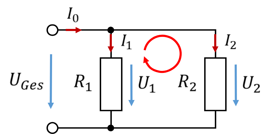
In a parallel connection, the current splits according to the node rule. More than two components can be connected in parallel.
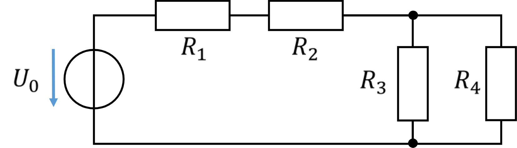
In the example circuit, you can check which components are connected in parallel. To do this, mentally sit on the upper terminal of the resistor R3. You can only reach the upper terminal of R4 via conductors. Then sit on the lower terminal of R3. You also reach the lower terminal of R4 only via conductors – i.e. without another component in the way. So these components are connected in parallel.
If you carry out the same test with R2 and R3, you will find that, seen from the upper terminal of R3, they are directly connected. Seen from the lower terminal of R3, however, the voltage source and R1 are in the way. Therefore R2 and R3 are not connected in parallel.
If the same circuit is drawn somewhat differently, the analysis becomes a little more difficult. In terms of its connections and function, the circuit diagram below corresponds exactly to the one above, but the arrangement of the resistors and the source is less well chosen. In this circuit, it looks at first glance as if R1 and R2 were connected in parallel, while the parallel connection of R3 and R4 can no longer be recognised as such at first glance.
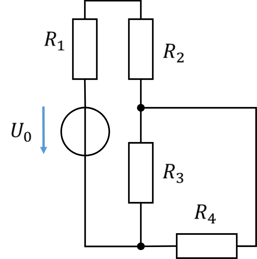
Note that not all components drawn parallel to each other are connected in parallel, and not all components drawn above or next to each other are connected in series.
In a parallel connection, too, the calculation would be simplified if both resistors could be combined into one that behaves in the same way as the parallel connection of two resistors. Here, too, the following applies: the behaviour of the equivalent resistor equals that of the parallel connection of the resistors if the voltage and current are the same in both circuits.
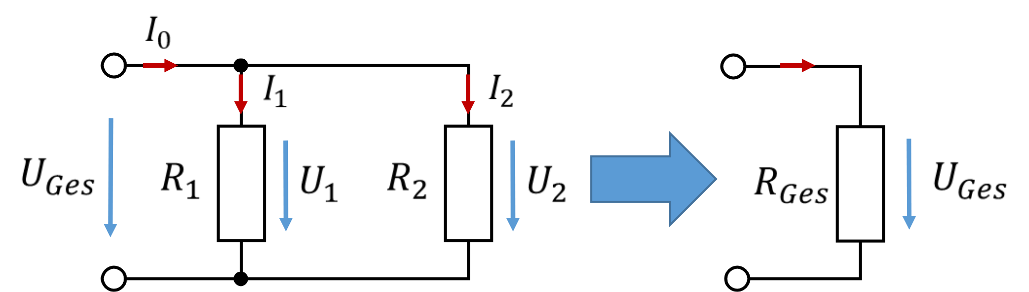
The current through the equivalent resistor RGes must equal the sum of the partial currents through R1 and R2. The following applies:
Because a sum appears in the denominator for resistors in parallel, the fraction cannot be rearranged as easily as for the series connection. The equation is easier to solve for conductances instead of resistances:
The short notation with the two vertical parallel lines is only intended to reduce writing effort. You use it in a calculation to indicate that two components are connected in parallel. What is always meant is the mathematically correct notation directly above. Example:
In a parallel connection, the following applies in principle: the equivalent resistance is smaller than the original resistances. In a series connection, it is the other way round.
For the voltages of two components connected in parallel, the following applies:
So for calculating the equivalent resistance, the same voltage is used in the numerator but a larger current in the denominator. That is why the equivalent resistance must always be smaller than the partial resistances.
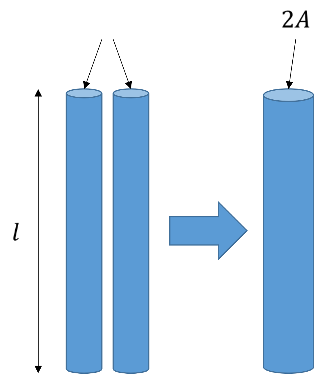
The parallel connection of resistors can be explained with the water model using two pipes running side by side. The difference in height of the pipes is the same, just as the voltage across two parallel resistors is the same. For simplicity, let us assume that both pipes have the same diameter, the same length and the same material parameter. If we try to describe both pipes by a single equivalent pipe with the same properties, we find: the area A of the equivalent pipe must be doubled.
For the resistance of a single pipe, the following applies:
The effective resistance – i.e. the obstruction of the water flowing through pipes due to a difference in height – has been halved by the parallel connection.
The example network from the previous chapter, in which the resistors in series have already been combined, can be simplified further. All four equivalent resistors are connected in parallel.
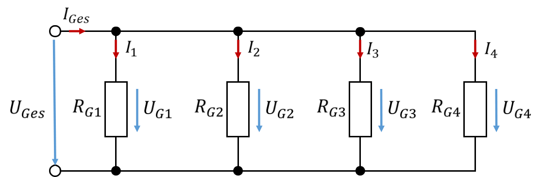

The circuit can be greatly simplified once again. In terms of voltage and current, the lower circuit behaves exactly like the upper circuit if the total resistance is calculated according to the rules of the parallel connection. At the resistor, the voltage and current of the overall circuit can easily be calculated with Ohm's law in one equation. That is a huge reduction in complexity. Every circuit consisting of linear components can be simplified in this way.
There is an online simulation on many electrical engineering topics that illustrates very well how voltage and current behave. The parallel connection of two resistors is simulated very nicely there. Please take a look at Falstad (https://www.falstad.com/circuit/) and select the following:
Circuits/Basics/Ohm's Law, Kirchhoff's Law 1
In the simulation, you see the level of the voltage as a colour: at the top of the source the 5 V in green, at the bottom at ground the 0 V in grey. The level of the current is shown as a movement of particles. You can see that more current flows through the low-resistance resistor than through the high-resistance one. You can set the values of the source and the resistors and observe where and how much current flows.
In the example "Mixed resistor circuits" directly below it in the selection menu, you will find a way to simulate series connections. You can create and observe series and parallel connections with switches. I think highly of this tool, because it explains electrical engineering graphically and without numbers. You will find illustrative examples on Falstad for many other topics in this tutorial.
Analogy between voltage, potential and heights
Potentials and voltages in meshes can be compared with the heights of rooms in a house. In the following figure, let us look at an electrical circuit on the right as an example with given voltages and potentials. The potentials are shown in red and the voltages in blue. The voltage of the source U0 = 5 V is divided into partial voltages across 5 resistors.
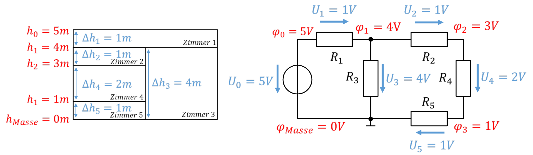
On the left, a house with rooms of different heights is shown. The rooms correspond to the resistors. The house is 5 m high in total. The total height of the house is divided into the partial heights of the rooms. The absolute heights of the room ceilings correspond to the values of the potentials in the circuit. The differences in height correspond to the voltages.
Room 1 takes up the entire top floor. Room 3 is as high as rooms 2, 4 and 5 together. These rooms are above or next to each other. A series connection corresponds to stacking rooms on top of each other. A parallel connection corresponds to arranging rooms next to each other.
The mesh equation of the right-hand mesh U3 = U2 + U4 + U5 can be transferred to the differences in height. The difference in height of room 3 evidently corresponds to the sum of the differences in height of rooms 2, 4 and 5.