Forms of Representation
Relationships can be represented in different ways, and each form of representation has advantages and disadvantages. If you have problems understanding something, it can help to switch the form of representation. For example, simulate a circuit that you do not understand, or simply sketch a difficult curve over time that is given as a formula.
The relationship between voltage and current at an ohmic resistor with R = 1 Ω is used as an example of different forms of representation in electrical engineering. The forms of representation all describe exactly the same thing, just on a different level.
Mathematical formula
The formula states the mathematical relationship for the calculation. U = R ∙ I applies. The formula shows the type of relationship between voltage and current. It follows the straight-line equation y = m ∙ x + b with y = U, x = I, m = R and b = 0 V. The straight-line equation describes a linear system. Voltage and current at a resistor are therefore linear.
Graph
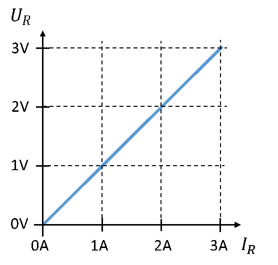
In the plot of voltage over current, the resistance value R determines the slope m between voltage and current. The type of relationship – the straight-line equation – is immediately visible in this representation. For example, you can read directly from the graph that the current at UR = 2 V has the value IR = 2 A, without having to calculate anything.
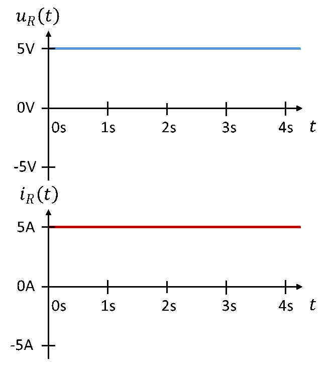
Voltage and current can also be shown as waveforms over time. The formula U = R ∙ I does not depend on time (it contains no parameter t), so the waveforms of voltage and current over time also have the same shape. A constant current of I = 5 A causes a constant voltage of U = R ∙ I = 1 Ω ∙ 5 A = 5 V across the resistor.
A sinusoidal voltage leads to a sinusoidal current.
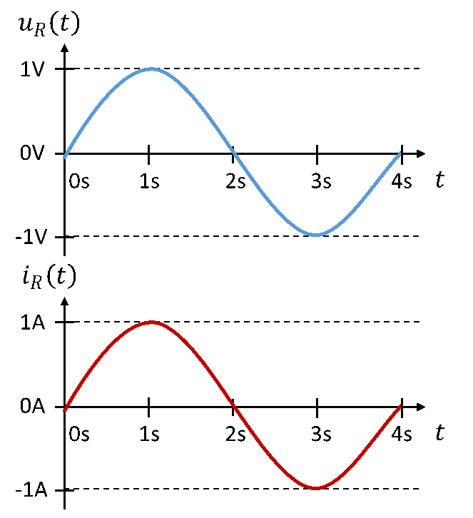
Waveforms help to get an idea of how, for example, AC voltage and AC current are related at components. A graphical representation can be seen as a visualisation of a mathematical relationship.
Circuit diagram
The circuit diagram shows all components, sources and connecting lines. The circuit diagram of the ohmic resistor consists of the resistor, its connecting leads, and the labels and directions of voltage and current. Specifying the direction of voltage and current is only reasonably possible in this representation. The sign in the mathematics then follows your definition of direction, with voltages and currents becoming positive or negative. A circuit diagram makes sense above all when several components are connected.
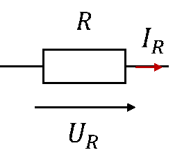
In the circuit diagram, patterns of known circuit structures such as voltage dividers can be recognised. This often allows the mathematics in the circuit to be simplified. In this representation, for example, you can recognise a parallel connection and conclude directly that the voltages across the components connected in parallel are equal, without having to calculate anything. The circuit diagram allows an experienced engineer to recognise the function of a circuit without having to calculate it mathematically. New circuits are usually first drawn as a circuit diagram.
Simulation model
A simulation model maps the circuit diagram in a simulation tool. Simulation makes it possible to determine currents and voltages at all components at the push of a button, without having to calculate them. To do this, the computer evaluates all mesh and node equations and calculates the relationship between voltage and current at the components (e.g. U = R ∙ I).
Changes to a circuit can easily be tried out in the simulation, because the effect of the change on the behaviour of the circuit can be seen immediately at the push of a button. Simulation is the most powerful form of representation, as it combines the circuit diagram, the results of the calculations and the graphical output of the waveforms of electrical quantities in one tool.
The real circuit
All the forms of description so far are theoretical in nature. They have become established because they are helpful in analysing and creating circuits. You can and should also build circuits for real. To do this, you connect sources and components with wires or traces on a circuit board. Voltage and current are determined by measurements, e.g. with a multimeter. The function of a circuit is only proven once you have built and tested it. Working on the real circuit is considerably more difficult than working in the simulation, but it is essential for solving practical problems.
Classic exams only work with the first three forms of representation. That is why the last two, which are the most important for your later work, are unfortunately under-represented in teaching and are not the focus of your exam preparation.