Inductor
The inductor is a central component in power electronics. It makes sense to understand its behaviour before we use it in almost every power electronics circuit.
Inertia
First, let us look at the phenomenon of inertia: inertia describes the property of moving bodies to keep moving even though they are no longer being driven. What does that mean? When you hit a tennis ball with a racket, it moves at high speed. The ball is driven by the stroke at the beginning of the movement. But why does the ball keep moving right after the stroke, even though nobody is hitting it any more?
The ball is inert. As soon as it has a velocity and no forces act on it, it keeps its velocity. We call people inert (sluggish) when they stay lying inactive on the couch and maintain their state of laziness. Inertia has a lot to do with “keeping the current state”. For moving bodies, the velocity remains unchanged.
In reality, every movement becomes slower. This is because there is always friction, which brakes the movement. The tennis ball slows down because the air rubs against it. In addition, gravity pulls it towards the earth. Both are external forces. If the tennis ball flew in space without gravity and without air friction, its velocity would indeed remain constant – because of its inertia.
A system with high inertia has the property that its velocity is difficult to change. It takes a long time to get it moving at all, and then it is also hard to stop it. In general, heavy objects are more inert than light ones. Try accelerating or braking a lorry. Now compare that with a small car. Inertia plays an important role for the inductor – or for its analogy in the water model.
In the water model, an inductor corresponds to a water wheel with a large mass and high inertia. Inertia in a rotational movement is also called “momentum”. The water wheel behaves like a flywheel. So a lot of force is needed to set it in motion. And once it is turning, it keeps turning at constant speed if it is neither driven nor braked any further.
The flywheel is an energy store. Energy has to be put in to make it turn. As soon as it turns, the energy is stored in the flywheel as kinetic energy.
To set the water wheel in motion, we let water flow from a high basin over the water wheel into a lower basin. In this thought model, the flow speed of the water is not limited by a pipe. The flow speed of the water is determined solely by the water wheel. The water cannot flow past the flywheel; it can only turn the wheel. The water always flows exactly as fast as the wheel turns.
At first the wheel is not turning. Because of the slope of the water, a pressure (force) acts on the wheel and it slowly begins to turn. As soon as the wheel turns, water flows at the speed set by the wheel. After all, the water cannot flow past the flywheel. The wheel turns faster and faster over time. The rotational speed of the water wheel is proportional to the flow speed of the water at the water wheel. In this way we “charge” the wheel with energy.
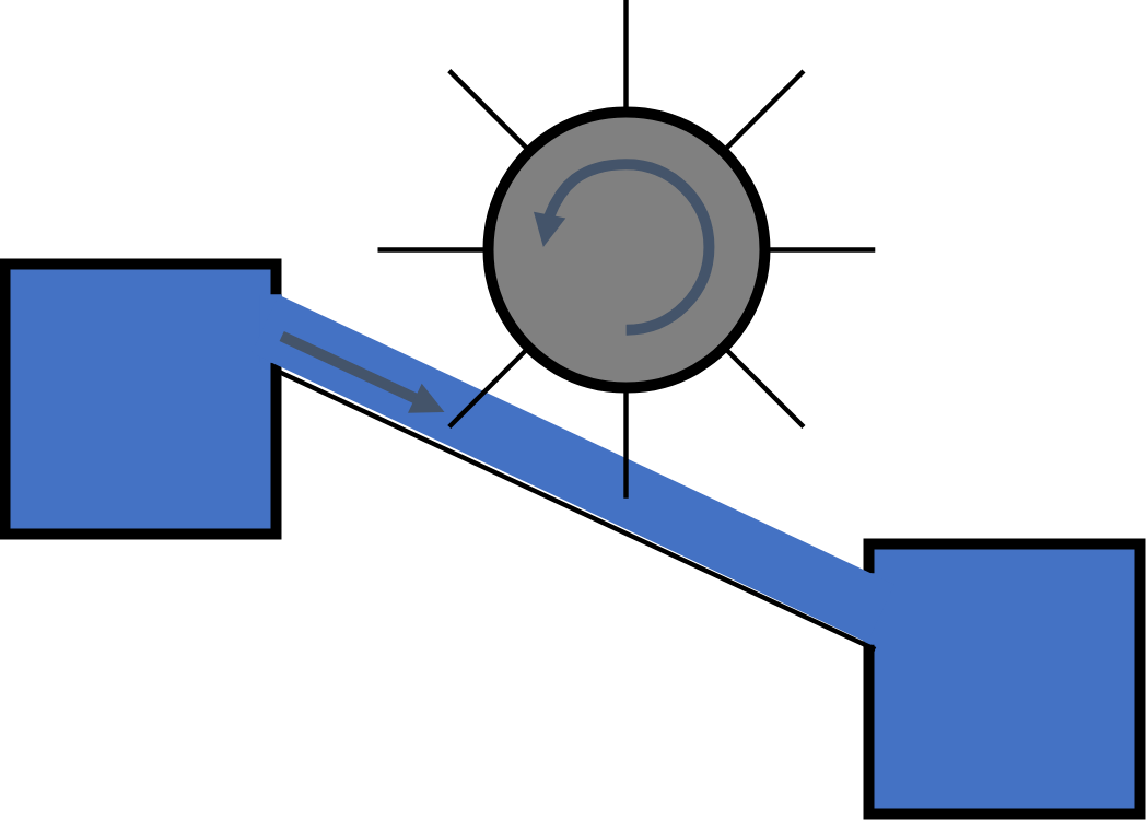
The slope of the water creates the pressure on the wheel. The steeper the slope, the more strongly the wheel accelerates. With greater acceleration, the speed rises faster. You can compare this with the difference in acceleration between a small car and a sports car.
We now place the water wheel in a water circuit. A pump pumps water up from a lower connection. For this, energy is fed into the system from outside. The water flows down a ramp and then reaches the water wheel. The water wheel starts to turn as soon as the water pressure of the pumped-up water reaches the wheel.
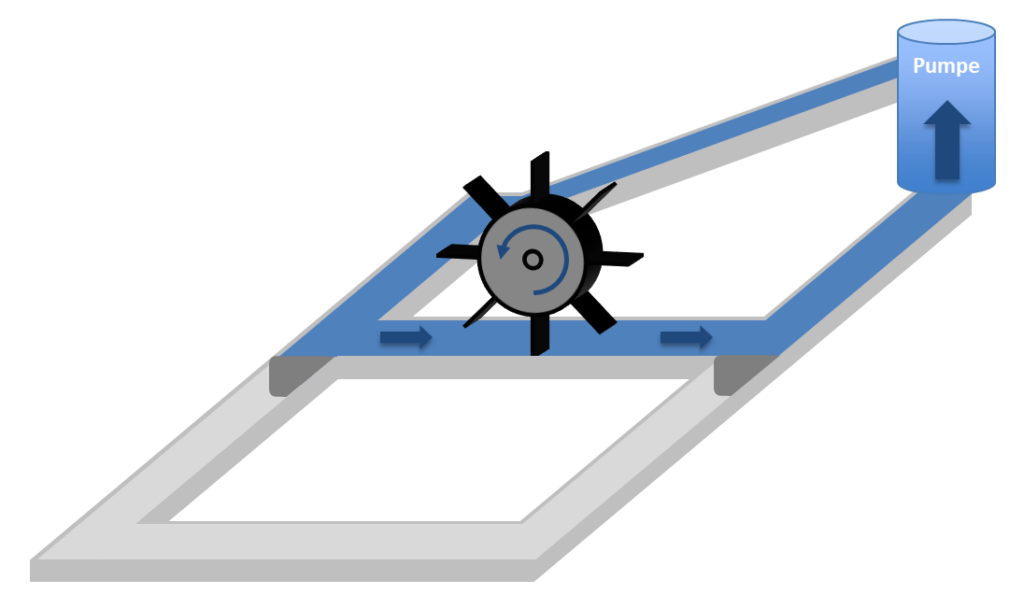
The water flows down a slope. In doing so, potential energy is converted into kinetic energy. The potential energy from the difference in height is stored in the flywheel. Since more and more energy is continuously fed into the system, the energy in the flywheel keeps rising. The flywheel therefore turns faster and faster. In a real system it reaches a maximum speed. In an ideal system the speed rises without limit. At first the water flows only in the upper, first part of the system.
The set-up is extended in the next figure. It is divided into two areas by adjustable flaps (dark grey). As soon as the flywheel has reached a certain rotational speed, we switch the flaps over and open the previously dry second part of the set-up to the water (see figure below). The flywheel is now separated from the pump. Because of its inertia or momentum, it keeps turning and now pushes water round in a circle in the second part of the set-up.
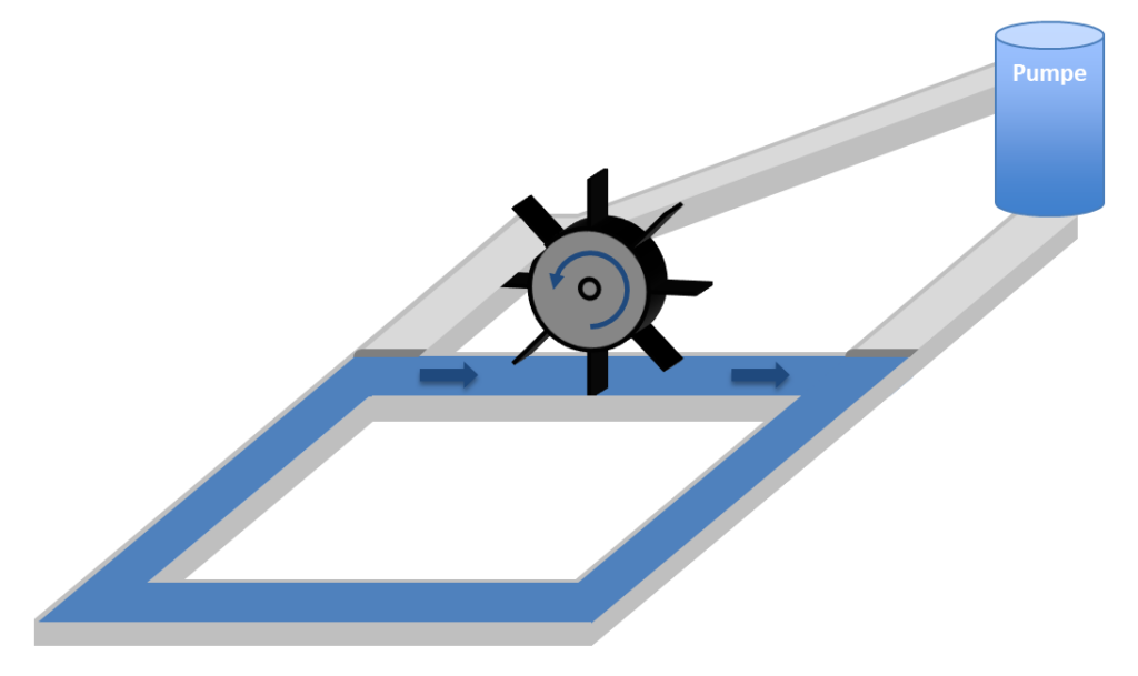
Since there is no slope for the water in the second part of the system, no energy is converted. In a real system with friction, the wheel slows down and eventually stops. In an ideal system without friction, the water keeps flowing round in a circle and the wheel keeps turning at constant speed.
So the flywheel decouples two subsystems. In the following example, the water in the second part of the set-up is conveyed up a ramp into a storage tank. The tank is at a different height from the upper pump connection. In the example, the outlet height of the tank is above the inlet height of the pump.
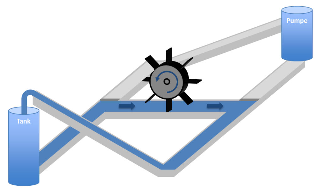
Again we consider the case in which the flywheel has previously been accelerated to a certain speed by the pump circuit. Then we switch over to the second area. As long as the wheel still has enough momentum, it pushes the water up the ramp into the tank. In doing so, kinetic energy from the rotation of the wheel is converted into potential energy, because the tank is higher than the flywheel.
The wheel now turns more and more slowly, even in an ideal system, and eventually comes to a standstill. After that, water flows from the tank “backwards” down the ramp. The flywheel now starts to turn the other way round. It accelerates in the other direction until the storage tank is empty. Of course we want to avoid this if the tank is to be filled.
In both water circuits: the change in the rotational speed of the water wheel over time is proportional to the slope of the water. The speed stays constant when the slope is 0. The speed rises as long as water flows downhill in the direction of flow, and it falls as long as water flows uphill in the direction of flow.
With the flywheel we have a way of raising water to any height. For continuous operation we have to switch back and forth between the two areas again and again. If the flywheel becomes too slow, we switch on the pump circuit. Then the flywheel accelerates again. Once it is fast enough again, we let it push water into the higher tank for a while.
The higher the tank, the longer the phases in which the pump charges the flywheel have to be, and the shorter the phases in which the tank is filled can be.